-39-
IC DESCRIPTION
Appendix
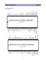
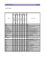
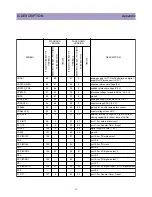
P1.6/SCL
108
7
21
84
port 1.6 or I
2
C-bus clock line
P1.7/SDA
109
8
20
83
port 1.7 or I
2
C-bus data line
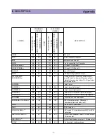
VDDP(3.3V)
110
9
19
82
supply to periphery and on-chip voltage
regulator (3.3 V)
P2.0/TPWM
111
10
18
81
port 2.0 or Tuning PWM output
P2.1/PWM0
112
11
17
80
port 2.1 or PWM0 output
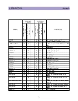
P2.2/PWM1
113
47
16
44
port 2.2 or PWM1 output
P2.3/PWM2
114
48
15
43
port 2.3 or PWM2 output
P3.0/ADC0
115
12
14
79
port 3.0 or ADC0 input
P3.1/ADC1
116
13
13
78
port 3.1 or ADC1 input
VDDC1
117
3
12
88
digital supply to core (+1.8 V)
DECV1V8
118
3
11
88
decoupling 1.8 V supply
P3.2/ADC2
119
14
10
77
port 3.2 or ADC2 input
P3.3/ADC3
120
15
9
76
port 3.3 or ADC3 input
VSSC/P
121
1
8
90
digital ground for m-Controller core and periphery
P2.4/PWM3
122
53
7
38
port 2.4 or PWM3 output
P2.5/PWM4
123
54
6
37
port 2.5 or PWM4 output
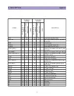
VDDC3
124
3
5
88
digital supply to core (1.8V)
VSSC3
125
1
4
90
ground
P1.2/INT2
126
2
3
89
port 1.2 or external interrupt 2
P1.4/RX
127
53
2
38
port 1.4 or UART bus
P1.5/TX
128
54
1
37
port 1.5 or UART bus
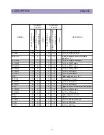
SYMBOL
STANDARD
VERSION
FACE DOWN
VERSION
DESCRIPTION
A
V
STEREO QFP128
FULL-STEREO/
MONO+ A
V
STEREO SSDIP90
MONO
A
V
STEREO QFP128
FULL-STEREO/
MONO+ A
V
STEREO SSDIP90
MONO
Summary of Contents for DTQ-29U1SCV
Page 7: ...6 CIRCUIT BLOCK DIAGRAM...
Page 27: ...26...
Page 28: ...27...
Page 31: ...30...
Page 32: ...31...
Page 33: ...32...

