-13-
ALIGNMENT INSTRUCTIONS
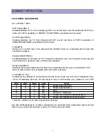
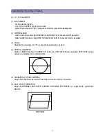
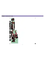
HOR WIDTH
adjust for 90% overscan.
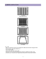
PARABOLA
CORNER B & CORNER T
EW TRAPEZ
3.7.7
AGC
- Make sure option bits are correct for the tuner fitted on the chassis (See above how to change option bits).
- Adjust the antenna signal level at 62 dB V± 2
- Tune a colour bar pattern.
- Find the “AGC LEVEL” item in service mode.
- Press the key “OK” on the remote keypad and wait until AGC level stabilise to the optimum value.
- Alternatively, use “Vol Up/Dwn” keys to adjust manually to the desired Tuner Take Over Point (TOP).
Summary of Contents for DTU-29M5ME
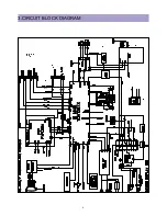
Page 5: ...4 3 CIRCUIT BLOCK DIAGRAM...
Page 16: ...15 5 CM 500 F TYPICAL SERVICE DATA...
Page 26: ...25...
Page 27: ...26...
Page 28: ...27...
Page 29: ...28...
Page 30: ...29 DTU 29M5...
Page 31: ...30 DTU 29M6...
Page 32: ...31 DTU 29M7...
Page 33: ...32 DTU 29U1...
Page 35: ...34 CM 500F 4858311110 DTU 29U8 4859645360 12W 8 SP 58126F DTU 29U8...
Page 36: ...35 DTU 29F1 CM 500F 4859845360 CPT A68AKY13X CM 500F CM 500F DTU 29F1...
Page 37: ...36 DTU 29F2 CM 500F 4859845360 CPT A68AKY13X CM 500F DTU 29F2...
Page 38: ...37 DTU 29F3 CM 500F 4859845360 CPT A68AKY13X CM 500F CM 500F DTU 29F3...
Page 40: ...39 IC DESCRIPTION...

