-44-
IC DESCRIPTION
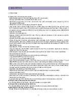
windows in parallel.
· Linear and non-linear horizontal scaling of the video signal to be displayed.
Sound Demodulation (all versions)
· Separate SIF (Sound IF) input for single reference QSS (Quasi Split Sound) demodulation.
· AM demodulator without extra reference circuit
· The mono intercarrier sound circuit has a selective FM-PLL demodulator which can be switched to the
different FM sound frequencies (4.5/5.5/6.0/6.5 MHz). The quality of this system is such that the external
band-pass filters can be omitted. In the stereo versions of UOCIII the use of this demodulator is optional
for special applications. Normally the FM demodulators of the stereo demodulator/decoder part are used
(see below).
· The FM-PLL demodulator can be set to centre frequencies of 4.72/5.74 MHz so that a second sound
channel can be demodulated. In such an application it is necessary that an external bandpass filter is
inserted.
· The vision IF and mono intercarrier sound circuit can be used for the demodulation of FM radio signals.
With an external FM tuner also signals with an IF frequency of 10.7 MHz can be demodulated.
· Switch to select between 2nd SIF from QSS demodulation or external FM (SSIF)
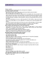
Audio Interfaces and switching (stereo versions with Audio DSP)
· Audio switch circuit with 4 stereo inputs, a stereo output for SCART/CINCH, 1 stereo output for
HEADPHONE. The headphone channel has an analogue volume control circuit for the L and R channel.
Finally 1 stereo SPEAKER output with digital controls.
· AVL (Automatic Volume Levelling) circuit for the headphone channel.
· Digital input crossbar switch for all digital signal sources and destinations
· Digital output crossbar for exchange of channel processing functionality
Stereo Demodulator and Decoder (full stereo versions)
· Demodulator and Decoder Easy Programming (DDEP)
· Auto standard detection (ASD)
· Static Standard Selection (SSS)
· DQPSK demodulation for different standards, simultaneously with 1-channel FM demodulation
· NICAM decoding (B/G, I, D/K and L standard)
· Two-carrier multistandard FM demodulation (B/G, D/K and M standard)
· Decoding for three analog multi-channel systems (A2, A2+ and A2*) and satellite sound
· Adaptive de-emphasis for satellite FM
· Optional AM demodulation for system L, simultaneously with NICAM
· Identification A2 systems (B/G, D/K and M standard) with different identification time constants
· FM pilot carrier present detector
· Monitor selection for FM/AM DC values and signals, with peak and quasi peak detection option
· BTSC MPX decoder
· SAP decoder
· dbx® noise reduction
· Japan (EIAJ) decoder
· FM radio decoder
· Soft-mute for DEMDEC outputs DEC, MONO and SAP
· FM overmodulation adaptation option to avoid clipping and distortion
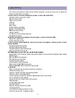
Audio Multi Channel Decoder (stereo versions with Audio DSP)
· Dolby® Pro Logic® (DPL)
Summary of Contents for DTU-29M5ME
Page 5: ...4 3 CIRCUIT BLOCK DIAGRAM...
Page 16: ...15 5 CM 500 F TYPICAL SERVICE DATA...
Page 26: ...25...
Page 27: ...26...
Page 28: ...27...
Page 29: ...28...
Page 30: ...29 DTU 29M5...
Page 31: ...30 DTU 29M6...
Page 32: ...31 DTU 29M7...
Page 33: ...32 DTU 29U1...
Page 35: ...34 CM 500F 4858311110 DTU 29U8 4859645360 12W 8 SP 58126F DTU 29U8...
Page 36: ...35 DTU 29F1 CM 500F 4859845360 CPT A68AKY13X CM 500F CM 500F DTU 29F1...
Page 37: ...36 DTU 29F2 CM 500F 4859845360 CPT A68AKY13X CM 500F DTU 29F2...
Page 38: ...37 DTU 29F3 CM 500F 4859845360 CPT A68AKY13X CM 500F CM 500F DTU 29F3...
Page 40: ...39 IC DESCRIPTION...

