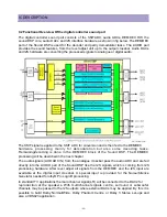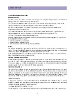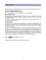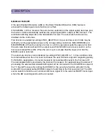
-53-
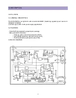
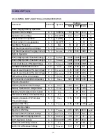
IC DESCRIPTION
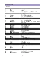
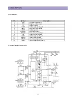
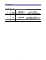
Terminal No.
Symbols
Descriptions
Functions
1
D
Drain terminal
MOSFET drain
3
S/GND
Source/Ground terminal
MOSFET Source/Ground
4
Vcc
Power supply
Input of power supply for control circiut
5
SS/OLP
Delay at Overload/Soft
Overload Protection and Soft
Start set up Terminal
Opetation Time set up
6
FB
Feedback terminal
Constant Voltage Control Signal Input,
Burst(intermittent) mode Oecillation Control
7
OCP/BD
Overcurrent Protection Input
Overcurrent Detection Signal Input
/Bottom Detection Terminal
/Bottom Detection Signal Input
6.4 PIN DESCRIPTION
Summary of Contents for DTU-29M5ME
Page 5: ...4 3 CIRCUIT BLOCK DIAGRAM...
Page 16: ...15 5 CM 500 F TYPICAL SERVICE DATA...
Page 26: ...25...
Page 27: ...26...
Page 28: ...27...
Page 29: ...28...
Page 30: ...29 DTU 29M5...
Page 31: ...30 DTU 29M6...
Page 32: ...31 DTU 29M7...
Page 33: ...32 DTU 29U1...
Page 35: ...34 CM 500F 4858311110 DTU 29U8 4859645360 12W 8 SP 58126F DTU 29U8...
Page 36: ...35 DTU 29F1 CM 500F 4859845360 CPT A68AKY13X CM 500F CM 500F DTU 29F1...
Page 37: ...36 DTU 29F2 CM 500F 4859845360 CPT A68AKY13X CM 500F DTU 29F2...
Page 38: ...37 DTU 29F3 CM 500F 4859845360 CPT A68AKY13X CM 500F CM 500F DTU 29F3...
Page 40: ...39 IC DESCRIPTION...

