-56-
IC DESCRIPTION
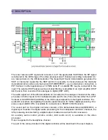
applied to obtain sufficient selectivity (the sound input can be activated by means of the setting
of CMB2-CMB0 bits in subaddress 4AH). The setting to the wanted frequency is realised by
means of the control bits FMA, FMB and FMC in the control bit 33H.
From the output status bytes it can be read whether the PL Lfrequency is inside or outside the
window and whether thePLL is in lock or not. With this information it is possible to make an
automatic search system for the incoming sound frequency. This can be realised by means of a
software loop which switches the demodulator to the various frequencies and then select the
frequency on which a lock condition has been found.
The amplitude deemphasis output signal changed with 6dB by means of the AGN bit. In this
way output signal differences between the 4.5 MHz standard (frequency deviation25 kHz) and
the other standards (frequency deviation50 kHz) can be compensated.
7.4 Audio input selector and volume contro
7.4.1 STEREO AND AV STEREO VERSIONS
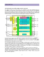
The audio input selector circuit has 4 external stereo inputs, a stereo output for SCART/CINCH
and stereo outputs for headphone and audio power amplifiers. The selection is made with the
bits SAS2/0, SO2/0 and HPO2/0. AV stereo versions without Audio DSP have no headphone
output. The input signal selection for the volume controlled audio outputs is realised by the
HPO2/0 bits.
The gain from an external audio input to each of the (non-controlled) analog output is 0 or
+6dB(controlled by the DSG bit). A supply voltage of 5V allows input and output amplitude of
1VRMS full scale, as required to comply with the SCART specification, the audio supply voltage
must be 8V. In that case the gain of the audio amplifier must be doubled. This can be realised
with the DSG bit in subaddress 32H.
The circuit contains an analogue stereo volume control circuit with a control range of about
70dB.
This volume control circuit is used for the headphone channel (stereo versions with Audio DSP)
or for the main channel (AV stereo versions without Audio DSP). The analogue control circuit
also contains an Automatic Volume Levelling(AVL) function. When this function is activated it
stabilises the audio output signal to a certain level so that big fluctuations of the output power
are prevented.
7.4.2 MONO VERSIONS
The audio input selector circuit has 4 inputs for mono signals. The selection is made with the
HPO2/0 bits.
The circuit contains an analogue volume control circuit with a control range of about 70dB and
an AVL circuit.
7.5 CVBS and Y/C input signal selection
7.5.1 ALL VERSIONS
Summary of Contents for DTU-29M5ME
Page 5: ...4 3 CIRCUIT BLOCK DIAGRAM...
Page 16: ...15 5 CM 500 F TYPICAL SERVICE DATA...
Page 26: ...25...
Page 27: ...26...
Page 28: ...27...
Page 29: ...28...
Page 30: ...29 DTU 29M5...
Page 31: ...30 DTU 29M6...
Page 32: ...31 DTU 29M7...
Page 33: ...32 DTU 29U1...
Page 35: ...34 CM 500F 4858311110 DTU 29U8 4859645360 12W 8 SP 58126F DTU 29U8...
Page 36: ...35 DTU 29F1 CM 500F 4859845360 CPT A68AKY13X CM 500F CM 500F DTU 29F1...
Page 37: ...36 DTU 29F2 CM 500F 4859845360 CPT A68AKY13X CM 500F DTU 29F2...
Page 38: ...37 DTU 29F3 CM 500F 4859845360 CPT A68AKY13X CM 500F CM 500F DTU 29F3...
Page 40: ...39 IC DESCRIPTION...

