


-65-
IC DESCRIPTION
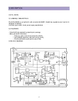
9.3 Demodulator and decoder
INTRODUCTION
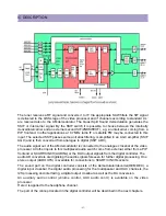
The TV sound processor provides an easy-to-use programming interface and built-in
intelligence for the demodulator and decoder part.
The sound demodulator is able to search for sound carriers and react to transmission mode
changes autonomously, without interaction of the micro controller software.
It is possible for a typical terrestrial TV application to setup the entire demodulator with
transmission of few control words.
The control interface still allows access to every detail, called demodulator expert mode, for
special applications such as satellite TV, more elaborated search algorithms etc.
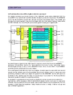
The new TV Sound Processor Demodulator and
Decoder Easy Programming(DDEP) interface provides three possible approaches to setup the
demodulator and decoder parts:
> Auto Standard Detection (ASD)
> Static Standard Selection (SSS)
> Demodulator and Decoder Expert Mode (DDXM)
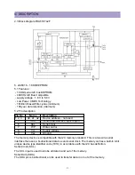
MIXER
The digitized 2nd SIF input signal is fed to the mixers, which mix one or both input sound carriers down to
zero IF. The mixer frequency is derived by the standard setting (Easy Programming) or in the Demodulator
and Decoder Expert Mode (DDXM) by a 24-bit control word for each carrier.
For NICAM demodulation, a feedback signal is added to the control word of the second carrier
mixer to establish a carrier-frequency loop.
FM AND AM DEMODULATION
An FM or AM input signal is fed via a band-limiting filter to a one of two demodulators that can
be used for either FM or AM demodulation. Four filters with different bandwidth are available.
The output signal of the first demodulator can be used for further demodulation of multiplex
signals used in the BTSC, EIAJ and FM Radio standards.
FM IDENTIFICATION
The identification of the FM sound mode is performed by AM synchronous demodulation of the pilot signal
and narrow-band detection of the identification frequencies. The result is available via the control bus
interface. A selection can be made for three different modes that represent different trade-offs between
speed and reliability of identification. The mode is set by DDEP (for FM two-carrier standards) or via
expert mode. DDEP also performs automatic FM de-matrix control in dependence on the identification.
FM/AM DECODING
A high-pass filter suppresses DC offsets from the FM/AM demodulators due to carrier
frequency offsets and supplies the monitor/peak function with DC values and an un-filtered
signal, e.g. for the purpose of carrier detection.
The audio bandwidth is approx. 15 kHz.
The de-emphasis function offers fixed settings for the supported standards (50s, 60s, 75s and J17).
Summary of Contents for DTU-29M5ME
Page 5: ...4 3 CIRCUIT BLOCK DIAGRAM...
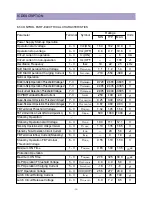
Page 16: ...15 5 CM 500 F TYPICAL SERVICE DATA...
Page 26: ...25...
Page 27: ...26...
Page 28: ...27...
Page 29: ...28...
Page 30: ...29 DTU 29M5...
Page 31: ...30 DTU 29M6...
Page 32: ...31 DTU 29M7...
Page 33: ...32 DTU 29U1...
Page 35: ...34 CM 500F 4858311110 DTU 29U8 4859645360 12W 8 SP 58126F DTU 29U8...
Page 36: ...35 DTU 29F1 CM 500F 4859845360 CPT A68AKY13X CM 500F CM 500F DTU 29F1...
Page 37: ...36 DTU 29F2 CM 500F 4859845360 CPT A68AKY13X CM 500F DTU 29F2...
Page 38: ...37 DTU 29F3 CM 500F 4859845360 CPT A68AKY13X CM 500F CM 500F DTU 29F3...
Page 40: ...39 IC DESCRIPTION...