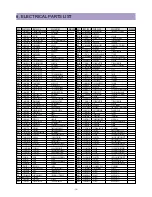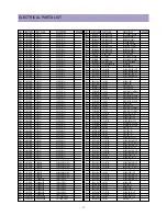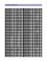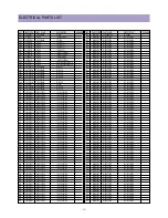
-6-
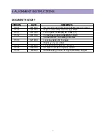
ALIGNMENT INSTRUCTIONS
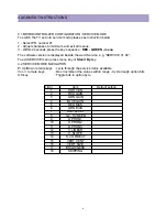
4.1MICROCONTROLLER CONFIGURATION : SERVICE MODE
To switch the TV set into service mode please see instruction below.
1 - Select PR. number 91
2 - Adjust sharpness to minimum and exit all menus.
3 - Within 2 seconds press the key sequence : RED - GREEN - menu
The software version is displayed beside the word Service, e.g. “SERVICE V1.00”.
To exit SERVICE menu press menu key or Stand By key.
4.2 SERVICE MODE NAVIGATION
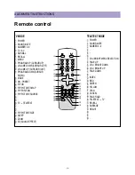
Pr Up/Down remote keys : cycle through the service items available.
Vol -/+ remote keys
: Dec./Increment the values within range - Cycle trough option bits.
OK key
: Toggle bits in option byte
Order
Item
Default setting
1
HOR CEN
2
RED GAIN
3
GRN GAIN
4
BLUE GAIN
5
RED BIAS
6
GRN BIAS
7
AGC LEVEL
8
G2 - SCREEN
9
OPTION1
10
OPTION2
11
OPTION3
12
V. LINEAR
13
V. SLOPE
14
S. CORRECT
15
VERT CENT
16
VERT SIZE
17
BRIGHINESS
18
SHIPPING
Summary of Contents for DTU-29M5ME
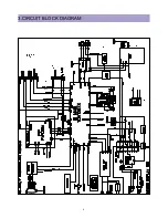
Page 5: ...4 3 CIRCUIT BLOCK DIAGRAM...
Page 16: ...15 5 CM 500 F TYPICAL SERVICE DATA...
Page 26: ...25...
Page 27: ...26...
Page 28: ...27...
Page 29: ...28...
Page 30: ...29 DTU 29M5...
Page 31: ...30 DTU 29M6...
Page 32: ...31 DTU 29M7...
Page 33: ...32 DTU 29U1...
Page 35: ...34 CM 500F 4858311110 DTU 29U8 4859645360 12W 8 SP 58126F DTU 29U8...
Page 36: ...35 DTU 29F1 CM 500F 4859845360 CPT A68AKY13X CM 500F CM 500F DTU 29F1...
Page 37: ...36 DTU 29F2 CM 500F 4859845360 CPT A68AKY13X CM 500F DTU 29F2...
Page 38: ...37 DTU 29F3 CM 500F 4859845360 CPT A68AKY13X CM 500F CM 500F DTU 29F3...
Page 40: ...39 IC DESCRIPTION...

