

-73-
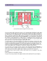
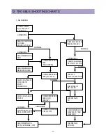
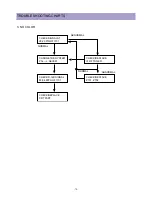
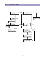
TROUBLE SHOOTING CHARTS
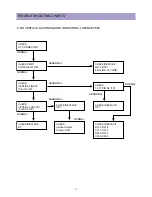
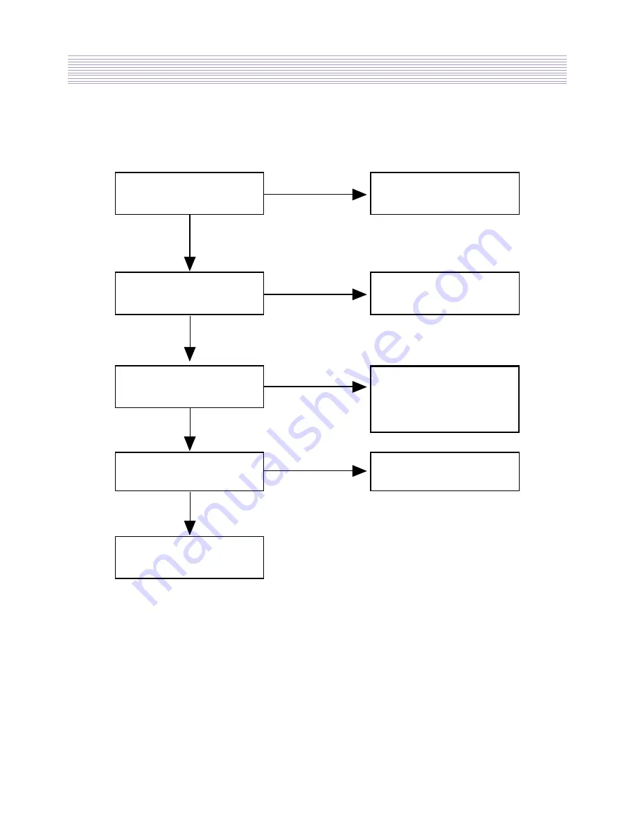
CHECK SIGNAL AT PIN
8,9,11,12, OF I601
CHECK SIGNAL AT PIN
2,4 OF I601
CHECK SIGNAL AT PIN
57,58, I701
NORMAL
NORMAL
NORMAL
NORMAL
NORMAL
ABNORMAL
ABNORMAL
ABNORMAL
ABNORMAL
CHECK SIF OUT OF
I701
CHECK
Speaker & Connector
Replade I601
CHECK/REPLACE
R602, R604,
R605, R606,
R606, C606
CHECK VOLTAGE AT PIN
33,34 OF I701
REPLACE TUNER
6. NO MAN SOUND(RF)
Summary of Contents for DTU-29M5ME
Page 5: ...4 3 CIRCUIT BLOCK DIAGRAM...
Page 16: ...15 5 CM 500 F TYPICAL SERVICE DATA...
Page 26: ...25...
Page 27: ...26...
Page 28: ...27...
Page 29: ...28...
Page 30: ...29 DTU 29M5...
Page 31: ...30 DTU 29M6...
Page 32: ...31 DTU 29M7...
Page 33: ...32 DTU 29U1...
Page 35: ...34 CM 500F 4858311110 DTU 29U8 4859645360 12W 8 SP 58126F DTU 29U8...
Page 36: ...35 DTU 29F1 CM 500F 4859845360 CPT A68AKY13X CM 500F CM 500F DTU 29F1...
Page 37: ...36 DTU 29F2 CM 500F 4859845360 CPT A68AKY13X CM 500F DTU 29F2...
Page 38: ...37 DTU 29F3 CM 500F 4859845360 CPT A68AKY13X CM 500F CM 500F DTU 29F3...
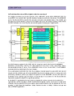
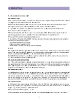
Page 40: ...39 IC DESCRIPTION...


