

-7-
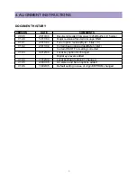
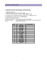
ALIGNMENT INSTRUCTIONS
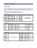
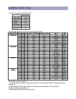
4.3.1 OPTION1
B7
B6
B5
B4
B3
B2
B1
B0
1
0
TOP
Teletext
OFF
FASTEXT
(FLOF)
OFF
TUBE
4:3
Dolby
Virtual
OFF
Teletext
ON
TUNER OPTIONS
(see table below)
TOP
Teletext
ON
FASTEXT
(FLOF)
ON
TUBE
16:9
Dolby
Virtual
ON
Teletext
OFF
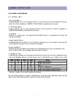
4.3.2 OPTION2
B7
B6
B5
B4
B3
B2
B1
B0
1
0
NEC
remote
control
AV out:
monitor
AV out:
Tuner
Koran
functions
enabled
Digital
eye
disabled
Digital
eye
enabled
PARS
logo
OFF
ON
Daewoo
Remote
control
Koran
functions
enabled
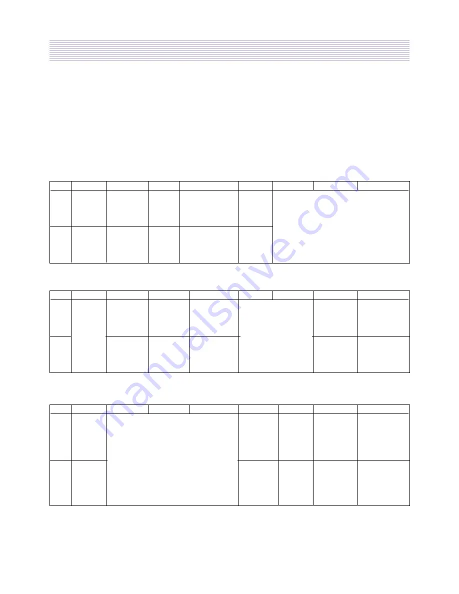
1 CONTROL BITS
There are two option bytes available (16 bits in all). These option bits are available from
FACTORY and SERVICE mode. First find the OPTION1, OPTION2 or OPTION3 control, and
then use the UP/DOWN and PLUS/MINUS keys on the relevant remote keypad to control the
bits.
The table below shows the three option bytes available.
Default setting in case of virgin EEPROM are shown in light grey.
Fixed to
‘0’
Local key option
(see table below)
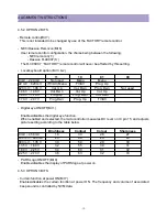
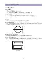
4.3.3 OPTION3
B7
B6
B5
B4
B3
B2
B1
B0
1
0
Beep at
curtain
opening:
OFF
PIP
OFF
PIP
ON
Chassis
with E/W
correction
circuit
Chassis
with out
E/W
correction
circuit
Beep at
curtain
opening:
ON
Full
stereo
AV
Stereo
only
Curtain
OFF
Curtain
On
Teletext language table
Summary of Contents for DTU-29M5ME
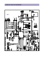
Page 5: ...4 3 CIRCUIT BLOCK DIAGRAM...
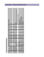
Page 16: ...15 5 CM 500 F TYPICAL SERVICE DATA...
Page 26: ...25...
Page 27: ...26...
Page 28: ...27...
Page 29: ...28...
Page 30: ...29 DTU 29M5...
Page 31: ...30 DTU 29M6...
Page 32: ...31 DTU 29M7...
Page 33: ...32 DTU 29U1...
Page 35: ...34 CM 500F 4858311110 DTU 29U8 4859645360 12W 8 SP 58126F DTU 29U8...
Page 36: ...35 DTU 29F1 CM 500F 4859845360 CPT A68AKY13X CM 500F CM 500F DTU 29F1...
Page 37: ...36 DTU 29F2 CM 500F 4859845360 CPT A68AKY13X CM 500F DTU 29F2...
Page 38: ...37 DTU 29F3 CM 500F 4859845360 CPT A68AKY13X CM 500F CM 500F DTU 29F3...
Page 40: ...39 IC DESCRIPTION...