CIRCUIT
12
1. VIDEO SIGNAL FLOW
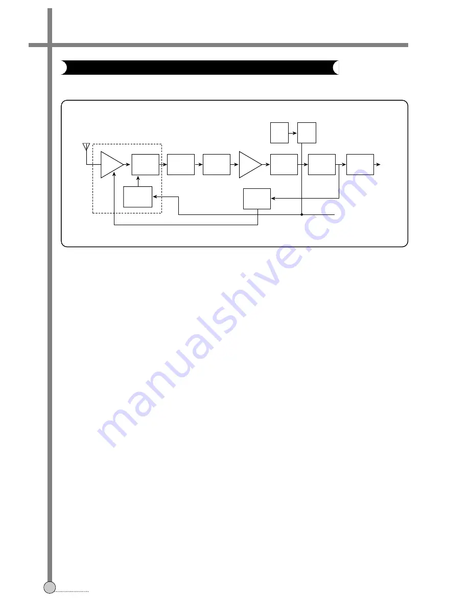
The signal from the ANT is amplified for selectivity, to decrease image interference, and increase S/N using the RF
AMP. The RF signal at the MIXER is subtracted from the LOCAL OSC frequency using the upperside band method, to
change is into the IF signal; 38.9MHz. The IF signal converted from the RF signal in the tuner block is amplified by
about 28dB to increase S/N in the pre-amp block. The reason for thesis that the SAW filter has its own insertion loss
of about-18 to -22dB. The SAW filter is a kind of BPF, used to remove the near channel harmonics and make the
desired frequency response. The IF AMP desired of about 60 to 70dB gain for receiver sensitivity and selectivity. The
vision IF AMP consists of three AC-coupled differential amplifier stages; each stage uses a controlled feedback
network called AGC. To maintain the video output signal at a constant level the automatic control voltage is generated
according to the transmission standard. For negative modulation in the PAL standard the peak-sync level is detected.
The AGC detector charges and discharges the AGC capacitor to set the IF gain and the tuner gain. We can also
adjust the tuner AGC voltage take over point. This allow the tuner and the IF SAW filter to be matched to achieve the
optimum IF input signal. The IF amplifier output signal is fed to a frequency detector and to a phase detector. The
frequency detector is operational before lock-in. A DC current is generated which is proportional to the frequency
difference between the input signal and the VCO frequency. The control voltage for the VCO is provided by the phase
detector. The demodulate output signal is fed via an integrated LPF (about 12MHz) to the video amplifier for
suppression of the carrier harmonics.
The VCO operates with a symmetrically-connected reference L-C circuit, running at the double vision carrier frequency
(77.8MHz) to decrease the frequency error. Fequency control is performed by an internal varicap diode. The voltage
used to set the VCO frequency to the actual double vision carrier frequency, is also amplified and converted to give the
AFC output current. The AFC output is fed to the µ-COM to change the LOCAL OSC frequency and for channel
searching. The VCO signal is divided by-two in a travelling wave divider, which generates two differenctial output
signals with exactly 90 degrees phase difference, independent of frequency. The video signal passing through the
5.5MHz sound trap is fed to the buffer.
3-4. IF C
IRCUIT
O
PERATION
RF
AMP
MIXER
PRE-
AMP
LOCAL
OSC
AGC
DET
SAW
FILTER
VIDEO DET
& DEMOD
TUNER
IF
AMP
SOUND
TRAP
VCO
AFC
BUFFER
VIDEO
OUT
µ
-COM
Summary of Contents for DV-K*84W Series
Page 71: ...CIRCUIT DIAGRAMS 68 SECTION 9 CIRCUIT DIAGRAM 9 1 CONNECTION DIAGRAM DV K884W K484W K284W...
Page 72: ...CIRCUIT DIAGRAMS 69 9 2 POWER CIRCUIT DIAGRAM DV K884W K484W K284W...
Page 73: ...CIRCUIT DIAGRAMS 70 9 3 SYSCON AND LOGIC CIRCUIT DIAGRAM...
Page 74: ...CIRCUIT DIAGRAMS 71 9 4 PIF CIRCUIT DIAGRAM DV K884W K484W K284W...
Page 75: ...CIRCUIT DIAGRAMS 72 9 5 IF MPX MODULE CIRCUIT DIAGRAM DV K884W K484W K284W...
Page 76: ...CIRCUIT DIAGRAMS 73 9 6 VIDEO AUDIO CIRCUIT DIAGRAM DV K884W K484W K284W...
Page 77: ...CIRCUIT DIAGRAMS 74 9 7 Hi Fi PRE AMP CIRCUIT DIAGRAM DV K884W K484W K284W...
Page 78: ...DISASSEMBLY 79 SECTION 11 DISASSEMBLY 11 1 PACKING ASS Y...


