1
TROUBLE SHOOTING FLOW CHART
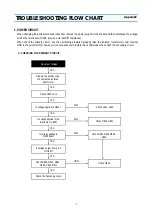
1. POWER CIRCUIT
When changing the parts which are broken first, remove the power plug from the socket and then discharge the voltage
across the terminals of C805. (Use an external K
§
Ù
resistance)
When check the primary circuit , use the oscilloscope isolated properly (Use the isolated transformer) and connect
GND to the primary GND, however it is not necessary to isolate the oscilloscope when check the secondary circuit.
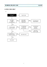
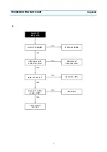
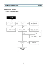
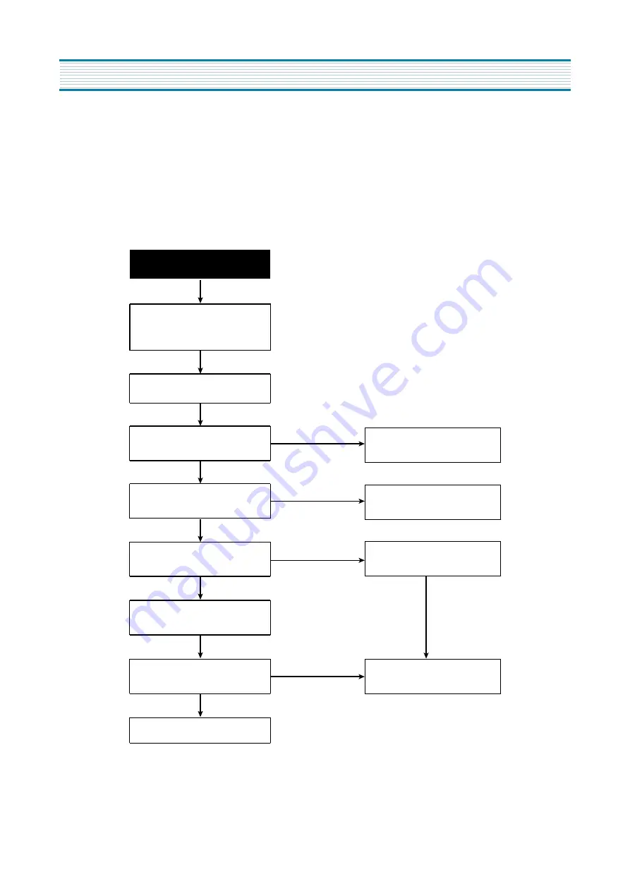
A. CHECKING THE PRIMARY CIRCUIT.
No output Voltage.
NO
NO
NO
YES
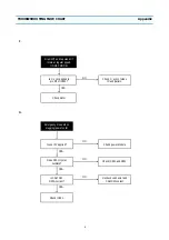
Prepare the oscilloscope
connected the isolated
transformer
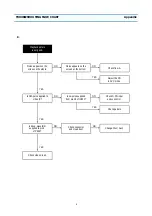
Check L801, L802
Check R803, D801
YES
YES
YES
YES
YES
YES
YES
YES
Check R804, R805,R806,
C806
Check F801 Fuse.
Is voltage applied to D801?
Is voltage applied to the
terminals of C805?
Is voltage applied to
Q801 base?
Is voltage output from pin 3
of IC801?
Check R809, R810, D804,
D805, C812, R811
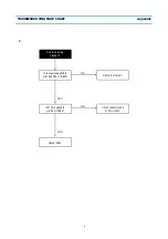
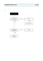
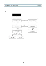
Check the Secondary circuit
Check Q802
Appendix
Summary of Contents for DV- K213S Series
Page 15: ...14 CIRCUIT DIAGRAM 1 POWER CIRCUIT DIAGRAM 230V ONLY...
Page 16: ...15 CIRCUIT DIAGRAM 2 SYSCON CIRCUIT DIAGRAM...
Page 17: ...16 CIRCUIT DIAGRAM 3 A V CIRCUIT DIAGRAM SECAM...
Page 18: ...17 4 PIF CIRCUIT DIAGRAM CIRCUIT DIAGRAM...
Page 19: ...18 CIRCUIT DIAGRAM 5 HIFI SW CIRCUIT DIAGRAM...
Page 20: ...19 CIRCUIT DIAGRAM 6 SW CIRCUIT DIAGRAM...
Page 25: ...24 COMPONENTS LOCATION GUIDE ON PCB BOTTOM VIEW 1 PCB MAIN...
Page 26: ...25 DISASSEMBLY 1 PACKING ASS Y...
Page 27: ...26 DISASSEMBLY 2 FRONT PANEL ASSEMBLY DV K813S SERIES DV K823S SERIES...
Page 28: ...27 DISASSEMBLY DV K873S SERIES DV K893S SERIES...
Page 29: ...28 DISASSEMBLY DV K843S SERIES DV K863S SERIES...
Page 30: ...29 DISASSEMBLY DV K9A3S SERIES...

