23
Some disassembly is required to access the adjustment locations. Refer to the "Disassembly Selection" in this publication for disassem-
bly instructions.
Caution: Use an isolation transformer when servicing.
Mechanical Checks/Gear Alignment
(Fig. 1, 2, 3, 4, 5)
When mechanical problems occur or when reassembling parts in this mechanism, be sure to confirm the following instructions to con-
firm the following:
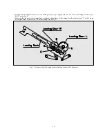
1. Make sure that the datum hole of the cam gear "A" is aligned with the hole "B" in the main base in the EJECT mode (Fig. 1).
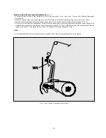
2. Make sure that the part of the relay lever "A" which is assembled with CONNECT PLATE is fully rotated up to the left end of the
hole "B" (Fig. 2).
Fig. 1 - Mechanical Checks/Cam Gear and F/L Alignment
Fig. 2 - Mechanical Checks/Relay Lever and Cam Gear Alignment
Summary of Contents for DV- K504N-SJ
Page 35: ...34 AC001 K584NZ SJ M K584NZ SG M only...
Page 36: ...35...
Page 37: ...36...
Page 38: ...37...
Page 39: ...38...
Page 60: ...59 ELECTRICAL ADJUSTMENTS Fig 1 Circuit Board Location...
Page 92: ...91 INTERCONNECT WIRING DIAGRAM K584N K484N K384N K284N...
Page 93: ...92 POWER SUPPLY SCHEMATIC DIAGRAM FREE VOLTAGE K584NY SJ M K584NZ SJ M K584NZ SG M...
Page 95: ...94 2HD HEAD AMP SCHEMATIC DIAGRAM K384N K284N K304N...
Page 96: ...95 4HD HEAD AMP SCHEMATIC DIAGRAM K584N K484N K504N...
Page 97: ...96 VIDEO AUDIO SCHEMATIC DIAGRAM K584N K484N K384N K284N K504N K304N...
Page 98: ...97 PIF INPUT SELECTOR SCHEMATIC DIAGRAM 9V USE K584NY SJ M K584NZ SJ M K584NZ SG M...
Page 100: ...99 TIMER SYSCON SCHEMATIC DIAGRAM K584N K484N K384N K284N K504N K304N...
Page 101: ...100 POWER SUPPLY BLOCK DIAGRAM FREE VOLTAGE K584NY SJ M K584NZ SJ M K584NZ SG M...
Page 103: ...102 2HD HEAD AMP BLOCK DIAGRAM K384N K284N K304N...
Page 104: ...103 4HD HEAD AMP BLOCK DIAGRAM K584N K484N K504N...
Page 105: ...104 VIDEO AUDIO BLOCK DIAGRAM K584N K484N K384N K284N K504N K304N...
Page 106: ...105 PIF INPUT SELECTOR BLOCK DIAGRAM K584N K484N K384N K284N K504N K304N...
Page 109: ...108 MAIN PCB 2HEAD 4HEAD...


