11
!
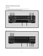
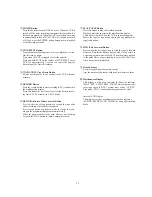
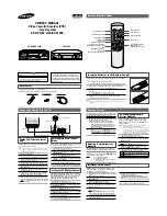
POWER Button
Press this button to turn the VCR on or off. When the VCR is
turned off, the timer recording is automatically turned on if it
has been programmed. When the VCR is turned on, the timer
is automatically turned off. The VCR will stop and be turned
off, if you press the POWER button during record, playback
or fast forward operation.
@
STOP/EJECT Button
Stops the normal functions such as record, playback, rewind,
fast-forward, or pause.
Press when the VCR is stopped to eject the cassette.
Press and hold STOP on the remote or STOP/EJECT on the
VCR for approximately 3 seconds to cancel the Express
Recording or the Timer Recording.
#
,
$
CHANNEL Up or Down Button
Selects next higher or lower channel in the VCR's channel
memory.
%
RECORD Button
Press the record button to start recording. REC is indicated in
the multifunction display.
Press this button (at least twice) to select the desired record-
ing time 0:30 (30 minutes) to 4:00 (4 hours).
^
REWIND (Reverse Picture Search) Button
Press this button at stop position to rewind the tape after
either recording or playback is completed.
Press rewind button at playback mode to reverse the scan-
ning on the programmed program material visibly.
When the picture reaches to the point where you are looking
for press the PLAY button to resume normal playback.
&
PLAY/PAUSE Button
Press this button to play the recorded material.
Playback indicator appears in the multifunction display.
This button is inactive when the VCR is in recording mode.
Pauses the tape for stop-action viewing during playback by
toggle this button.
*
FWD (Fast Forward) Button
Press this button at stop position to wind the tape to forward
direction. Press this button at playback mode for an access to
a wanted program material visibly. When the picture reached
to the point where you are looking for, press the PLAY but-
ton to resume normal playback.
(
Remote Sensor
Receives signals from the remote control.
Aim the remote at this sensor with no objects between them.
)
Multifunction Display
This display is used as an indicator for Function indicator
(PLAY, REC, F.FWD, REW, PAUSE), timer program indi-
cator tape speed (SP, EP), present time of day, VCR/TV,
Line mode (VID 1), channel number, tape counter, clock
In caseof LED Display.
This display is used as an indicator for function indicator.
(POWER, RECORD, VCR, TIMER) by using light emitting
diode.
Summary of Contents for DV- K584N-SJ
Page 35: ...34 AC001 K584NZ SJ M K584NZ SG M only...
Page 36: ...35...
Page 37: ...36...
Page 38: ...37...
Page 39: ...38...
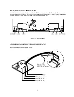
Page 60: ...59 ELECTRICAL ADJUSTMENTS Fig 1 Circuit Board Location...
Page 92: ...91 INTERCONNECT WIRING DIAGRAM K584N K484N K384N K284N...
Page 93: ...92 POWER SUPPLY SCHEMATIC DIAGRAM FREE VOLTAGE K584NY SJ M K584NZ SJ M K584NZ SG M...
Page 95: ...94 2HD HEAD AMP SCHEMATIC DIAGRAM K384N K284N K304N...
Page 96: ...95 4HD HEAD AMP SCHEMATIC DIAGRAM K584N K484N K504N...
Page 97: ...96 VIDEO AUDIO SCHEMATIC DIAGRAM K584N K484N K384N K284N K504N K304N...
Page 98: ...97 PIF INPUT SELECTOR SCHEMATIC DIAGRAM 9V USE K584NY SJ M K584NZ SJ M K584NZ SG M...
Page 100: ...99 TIMER SYSCON SCHEMATIC DIAGRAM K584N K484N K384N K284N K504N K304N...
Page 101: ...100 POWER SUPPLY BLOCK DIAGRAM FREE VOLTAGE K584NY SJ M K584NZ SJ M K584NZ SG M...
Page 103: ...102 2HD HEAD AMP BLOCK DIAGRAM K384N K284N K304N...
Page 104: ...103 4HD HEAD AMP BLOCK DIAGRAM K584N K484N K504N...
Page 105: ...104 VIDEO AUDIO BLOCK DIAGRAM K584N K484N K384N K284N K504N K304N...
Page 106: ...105 PIF INPUT SELECTOR BLOCK DIAGRAM K584N K484N K384N K284N K504N K304N...
Page 109: ...108 MAIN PCB 2HEAD 4HEAD...


