17
Component Descriptions
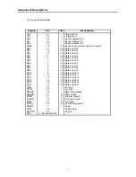
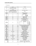
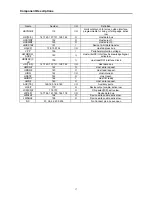
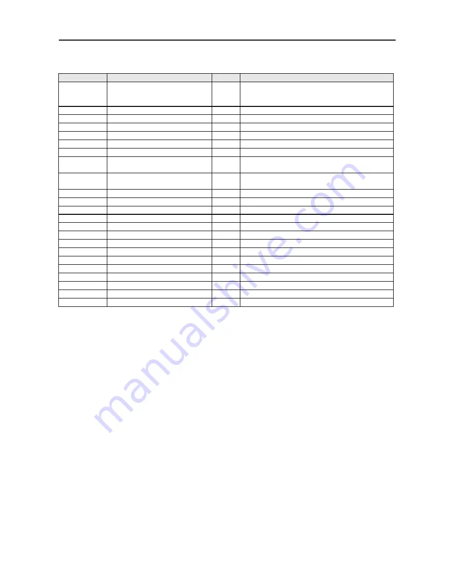
Name
Number
I/O
Definition
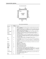
HSYNCH#
119
I/O
Horizontal synch for screen video interface,
programmable for rising or falling edge, active
low.
HD[15:0]
141:140, 137:131, 128:122
O
Host data bus
HCS1FX#
152
O
Host select 1.
HCS3FX#
153
O
Host select 3.
HIOCS16#
151
I
Device 16-bit data transfer.
HA[2:0]
158, 155:154
I/O
Host address bus.
VPP
159
I
Peripheral protection voltage.
HWR#/DCI_
ACK#
149
I,I
Host write/DCI Interface Acknowledge Signal,
active low.
HRD#DCI_C
LK
150
I,I
Host read/DCI Interface Clock.
HD[15:0]
141:140, 137:131, 128:122
I/O
Host data bus.
HWRQ#
142
O
Host write request.
HRDQ#
143
O
Host read request.
HIRQ
144
I/O
Host interrupt.
HRST#
145
O
Host reset.
HIORDY
146
I
Host I/O ready
HWR#
149
O
Host write request.
AUX[7:0]
169:165, 162:160
I/O
Auxiliary ports.
LOE#
170
O
Device output enable, active low.
LCS[3:0]#
176:173
O
Chip select[3:0], active low.
LD[15:0]
197:194, 191:185, 182:178
I/O
Device data bus.
LWRLL#
198
O
Device write enable, active low.
LWRHL#
199
O
Device write enable, active low.
NC
37, 38, 42, 203:202
No Connect pins. Leave open
Summary of Contents for DVC-T6300N
Page 10: ...10 2 1 3 NTSC PAL Digital Video Encoder AD7170 Component Descriptions ...
Page 11: ...11 Component Descriptions ...
Page 12: ...12 Component Descriptions ...
Page 14: ...14 Functional Description Component Descriptions ...
Page 15: ...15 Component Descriptions Pinout Diagram ...
Page 18: ...18 Block Diagram Component Descriptions 2 1 5 DIGITAL TO ANALOG STEREO AUDIO CONVERTER CS4391 ...
Page 19: ...19 Component Descriptions ...
Page 20: ...20 Component Descriptions ...
Page 21: ...21 Component Descriptions ...
Page 28: ...28 Component Descriptions ...
Page 30: ...30 Component Descriptions ...
Page 31: ...31 Component Descriptions ...
Page 54: ...54 9 PCB Diagrams 9 1 Main PCB Top ...
Page 55: ...55 PCB Diagrams 9 2 Main PCB Bottom ...
Page 56: ...56 9 3 Front PCB Top 9 4 Front PCB Bottom PCB Diagrams ...
Page 57: ...57 9 5 SMPS PCB Top 9 6 SMPS PCB Bottom PCB Diagrams ...
Page 58: ...58 10 Wiring Diagram ...
Page 65: ...65 11 3 SMPS PCB Schematic Diagram 11 3 SMPS PCB Schematic diagram ...
Page 66: ...66 1 27MHz 2 ROM DATA BUS 3 RAM DATA BUS 4 12C CLK 5 12C DATA 6 HSYNC 12 Oscillograms ...
Page 67: ...67 7 VSYNC 8 BCLK DVD 9 LRCK DVD 10 TSDO 11 MCLK 12 HOST DATA Oscillograms ...
Page 68: ...68 13 HOST CLK 14 HOST CS 15 MC DACO 16 MD DACO 17 VFD DATA 18 VFD STB Oscillograms ...
Page 70: ...70 MEMO ...


