


5. DIRECTIONS FOR DISASSEMBLY AND ADJUSTMENT
12
DIRECTIONS
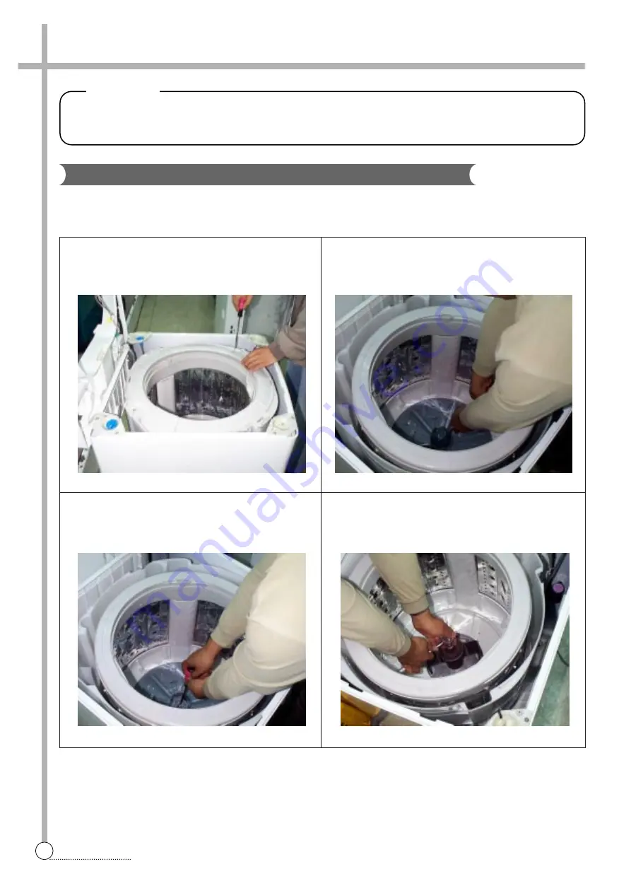
Gear Mechanism Ass’y Replacement
BEFORE ATTEMPTING TO SERVICE OR ADJUST ANY PART OF THE WASHING MACHINE, DISCONNECT
THE POWER CORD FROM THE ELECTRIC OUTLET.
W
Wa
ar
rn
ni
in
ng
g
1
Raise the top plate on the outer cabinet.
2
Loosen four screws mounting outer tub cover and
remove outer tub cover from the tub ass’y.
4
Loosen the pulsator mounting screw and remove the
pulsator.
3
Remove the cap pulsator from the pulsator assy by
using screw driver
5
Remove the special nut by using “T” type box wrentch.
6
Remove the special washer.
GEAR MECHANISM ASSY REPLACEMENT
Summary of Contents for DWF-200M
Page 31: ...30 WIRING DIAGRAM APPENDIX Wiring Diagram non Pump Single Valve ...
Page 32: ...31 WIRING DIAGRAM Non Pump Multi Valve ...
Page 33: ...32 WIRING DIAGRAM Pump Single Valve ...
Page 34: ...33 WIRING DIAGRAM Multi Valve ...
Page 35: ...34 PARTS DIAGRAM Inverter Single Valve ...
Page 36: ...35 PARTS DIAGRAM Parts Diagram ...
Page 37: ...36 PARTS DIAGRAM ...
Page 38: ...37 PARTS DIAGRAM ...
Page 39: ...38 PARTS DIAGRAM ...
Page 44: ...43 CIRCUIT DIAGRAM Circuit Diagram 201M ...
Page 45: ...44 CIRCUIT DIAGRAM Circuit Diagram 200M 240M ...
Page 46: ...45 CIRCUIT DIAGRAM Circuit Diagram 200MV 240MV ...


