20
THE REPAIR
No.
Process
Notice
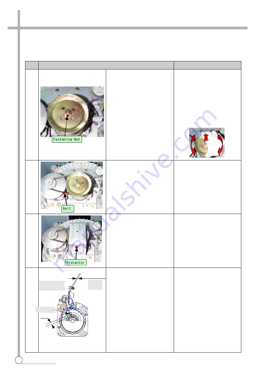
Assemble 2
5
6
7
8
Clutch Tip
Drain
Valve
Synchronous
Motor
3.5~4.5
keep distance 2~3mm
Assemble the fastening nut
Assemble the Belt
Assemble the protector
Final checking
- Use fixing jig and 17mm
socket wrench
as if disassembling,
as fastening torque about
100~200kgf-cm.
- Check the end-play, up and
downward and check the bind-
ing force, too much or not on
bi-direct of rotation.
Finally, check the distance
between brake lever and con-
trol bolt. (2~3mm)
Also, check the interferance
depth both clutch tip and clutch
boss(3.5~4.5mm)
Summary of Contents for DWF-200M
Page 31: ...30 WIRING DIAGRAM APPENDIX Wiring Diagram non Pump Single Valve ...
Page 32: ...31 WIRING DIAGRAM Non Pump Multi Valve ...
Page 33: ...32 WIRING DIAGRAM Pump Single Valve ...
Page 34: ...33 WIRING DIAGRAM Multi Valve ...
Page 35: ...34 PARTS DIAGRAM Inverter Single Valve ...
Page 36: ...35 PARTS DIAGRAM Parts Diagram ...
Page 37: ...36 PARTS DIAGRAM ...
Page 38: ...37 PARTS DIAGRAM ...
Page 39: ...38 PARTS DIAGRAM ...
Page 44: ...43 CIRCUIT DIAGRAM Circuit Diagram 201M ...
Page 45: ...44 CIRCUIT DIAGRAM Circuit Diagram 200M 240M ...
Page 46: ...45 CIRCUIT DIAGRAM Circuit Diagram 200MV 240MV ...