background image

33

PARTS DIAGRAM

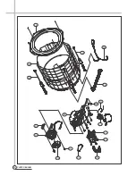
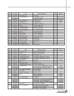
D01

3611413910

COVER TUB O

RECYCLE-PP, DWF-1398

1

D02

3618807105

TUB O

DWF-12,13KG, SINSUNG

1

D03

3613265901

HOSE BUBBLE

L=1250MM, ID=4

1

D04

3619803910

SUSPENSION AS(B)

DWF-1398, WHITE, BACK, VE TYPE

2

D05

3619803810

SUSPENSION AS(F)

DWF-1398, YELLOW, BACK, VE TYPE

2

D06

3613212120

HOSE DRAIN I

EVA,L=184

1

PUMP

D07

3610387400

BASE

SECEN 2.0T

1

D08

3616007001

SPECIAL SCREW

SCM 24H, 6.5*24

12

D09

3612757030

HARNESS EARTH INNER

L ID=4.3,R ID=8.3,L=810

1

D10

36196S1B50

DRAIN MOTOR

120-127V,SV-KL6T13D,KET#1806,L1150,BL

1

127V

36196L1B50

220V,SV-MX7T16D,KET#1806,L1150,BL

220~240V

D11

3617310600

GEAR MECHANISM(SP)

GM-1500-KS6P2

1

D12

7341801511

BOLT HEX

6B-1 8*15 MFZN

4

D13

3618346001

PROTECTOR GEAR

SGCC 1.2T, G/S

1

D14

3616590250

BELT V

M21, AGING 50HZ

1

50Hz

3616590240

M20.5, AGING 60HZ

60Hz

D15

3611502700

CUSHION DOWN

POM(8MM)

2

D16

3964221250

MOTOR CONDENSER

W1D50CA013,110~127/60 TAIWAN 1450L #1806(MG620427)

1

127V/60Hz

3964510320

WM244BA011 1450L #1806(MG620427)

220V/50Hz

3964320920

WM244GA011 AC 220V/60HZ 1450L(#1806 KET MG620427 )

220V/60Hz

D17

7650802528

BOLT HEX

6B-1 8*25 PW(3*28) MFZN

4

D18

3618401400

PULLEY MOTOR AS

M-TYPE(AL), DS=10 DP=48.5 60HZ

1

127V/60Hz

3618431300

M-TYPE DS=12 DP=60.5 50HZ

220V/50Hz

3618403510

M-TYPE DS=12 DP=52.5 60HZ

220V/60Hz

No.

Item Code

Item

Materials and Sizes

Q'TY

Remarks

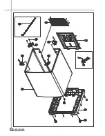
C01

3616104000

BALANCER AS

DWF-1094

1

C02

3612504700

GUIDE FILTER AS

13KG MAGIC 1 PIECE

2

MAGIC FILTER

3612504600

13KG LINT 1 PIECE

2

LINT FILTER

C03

3611911500

MAGIC FILTER AS

10KG 1 PIECE

2

Option

C04

3611903130

FILTER LINT

NYLON 226X113

2

Option

C05

3616051629

SPECIAL SCREW

SUS430 T2 TRS 5.5*16

12

C06

3618831410

TUB *I

SUS 0.4X398.5X1636

1

C07

3616051629

SPECIAL SCREW

SUS430 T2 TRS 5.5*16

12

C08

7122400829

SCREW TAPPING

T2S TRS 4X8 STS430

2

C09

7122400829

SCREW TAPPING

T2S TRS 4X8 STS430

2

C10

3618831500

TUB *U

13KG 1 PIECE FRPP

1

C11

3616063700

SPECIAL NUT

ZDC1 EU SAMWOO

1

C12

3617200600

FLANGE TUB

ALDC12 VE1,6POINT

1

C13

3616007001

SPECIAL SCREW

SCM24H,6.5*24 101S

6

C14

3610920100

CAP AGITATOR

ABS, 202AX

1

C15

3616062629

SPECIAL SCREW

STS430 6X26.5

1

C16

3610920000

CAP IMPELLER

ABS, 202AX

1

C17

3611885600

FAN IMPELLER

PP

1

C18

3619708610

PULSATOR AGITATOR

202AX, 202AX

1

No.

Item Code

Item

Materials and Sizes

Q'TY

Remarks

Summary of Contents for DWF-H361ASA

Page 1: ...4 Caution In this Manual some parts can be changed for improving their performance without notice in the parts list So if you need the latest parts information please refer to PPL Parts Price List in...

Page 2: ...O WASHER AUTO WASHER AUTO WASHER WASHING MACHINE Contents 1 SPECIFICATIONS 2 2 STRUCTURE OF THE WASHING MACHINE 3 3 DIRECTIONS FOR INSTALLATION AND USE 4 HOW TO INSTALL ON AN INCLINED PLACE 4 HOW TO C...

Page 3: ...PULSATOR 6 WINGS 406mm 11 WATER LEVEL CONTROL ELECTRONICAL SENSOR 12 GEAR MECHANISM ASS Y HELICAL GEAR 13 MAGIC FILTER O 14 SOFTENER INLET O 15 FUNCTION FOR SOAK WASH O 16 ALARM SIGNAL O 17 RESIDUAL...

Page 4: ...ings in this book may vary from your washer model They are designed to show the different features of all models covered by this book Your model may not include all features COLD WATER TAP After using...

Page 5: ...adjustable leg let the washer put down to the ground Keep the machine body more than 25cm 9 85inches apart from the wall surface It will make easy cleaning the drain filter which is equipped at the ba...

Page 6: ...filter is not cleaned at proper time every 10 times of use Drain problem could be caused 1Put down the remained water in the hose And put a container under the filter to collect water 2Turn the cap co...

Page 7: ...he adoption of the water currents to adjust the unbalanced load 5 One touch operation system Water Current to Adjust the Unbalanced Load It is a function to prevent eccentricity of the clothes after w...

Page 8: ...he time remembered by micom Draining Good draining The washer begins spin process after drainage condition Bad draining Draininig time is prolonged No draining Program is stopped and gives the alarm D...

Page 9: ...rinsing process the water below the pulsator fans creates a water currents as shown in figure The water is then discharged from the upper part of the tub through the water channel About 40 L min water...

Page 10: ...from motor and condition of pulling is held by operation of the lever 6 When the power is turned off the drain valve is closed because the wire returns to original position STRUCTURE Much lint may be...

Page 11: ...gear Internal gear Semi Pulsator 1 revolution 5 revolutions Gear pulley V belt Gear unit as Motor Motor 1800 r p m 60Hz Gear Unit as Directly V Belt Tub 710 740r p m 60Hz Pulsator 125 140r p m 60Hz Sp...

Page 12: ...LECTRIC OUTLET Warning GEAR MECHANISM ASS Y REPLACEMENT 1Raise the top plate on the outer cabinet 2Loosen four screws mounting outer tub cover and remove outer tub cover from the tub ass y 4Loosen the...

Page 13: ...CTIONS 7Remove the tub i assy qRemove four special bolt of gear mechanism assy by using a box wrentch 8Lay the front of the washer on the floor 9Remove four special bolts of gear protect by using a bo...

Page 14: ...THE CLUTCH BOSS ASSEMBLY Tool name Specification Q ty Fixing jig 1 Ratchet handle 1 Socket and extension bar socket 10mm 17mm per each Cotton yarn some the structure of gear mechanism Bearing Clutch...

Page 15: ...TION OF SPIN TUB IF THE SPIN TUB DOES NOT REVOLVE AND ONLY THE PULSATOR IS TURNING THAT IS CLUTCH SPRING DEFECT 2 TO CHECK THE SPIN SPEED RPM BETWEEN SPIN TUB AND PULSATOR IF YOU FIND THE DIFFERENT SP...

Page 16: ...t Remove the protector Remove the v belt Loosen the fastening nut Disassemble the spring washer Use wrench or driver ratchet handle extension bar socket 10mm Use fixing jig for pulley as to see fig 1...

Page 17: ...lutch boss assembly Separate coupling from clutch boss ass y Cleaning Catch the boss and pull upward with spiral rotate in the clockwise direction Clean the drum plate coupling surface and contact fac...

Page 18: ...asher Check the uneven face of coupling is assembled upward Push in the clutch boss ass y with rotating on the clockwise direction After assembling rotate on the clockwise more 2 3 teeth and pull out...

Page 19: ...ng Use fixing jig and 17mm socket wrench as if disassembling as fastening torque about 100 200kgf cm Check the end play up and downward and check the binding force too much or not on bi direct of rota...

Page 20: ...from the case filter ass y 6 separate the cavitation hose from the case filter ass y 7 assemble the case filter ass y that purchased 8 tie up three screws 9 tie up two screws 0 assemble the hose drai...

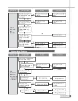
Page 21: ...tive Lead wire is defective SOLUTION Change water inlet valve Open the water tap Clean the filter Increase the water pressure Connect the connector or the terminal properly Change the P C B AS Change...

Page 22: ...ration Change the air tube Air tube is defective Change the pressure switch Pressure switch is defective PROBLEM THE PULSATOR DOES NOT ROTATE EVEN IF THE WATER IS SUPPLED CHECK POINT Does the motor op...

Page 23: ...ing Is the output voltage of the drain motor normal CAUSE SOLUTION Install the drain hose properly Remove the foreign substance from the drain housing Change the drain motor Change the P C B ASS Y Imp...

Page 24: ...tor terminal good CAUSE SOLUTION Close the lid Change the door switch Change the safety switch Connect the connector properly Change P C B ASS Y Change the drain motor Change the P C B ASS Y Change th...

Page 25: ...P C B ASS Y Is the strange noise generated when the pulsator rotates in TEST MODE of P C B ASS Y Is the V belt worn out CAUSE SOLUTION Connect the plug Change P C B ASS Y Change Fuse Connect the conn...

Page 26: ...switch is inferior The load sensing is inferior After the load sensing operates about 7 seconds the message is displayed during 0 5 second and water level is always fixed high The water level sensing...

Page 27: ...APPENDIX 26 PCB ASS Y Wiring Diagram...

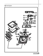
Page 28: ...S DIAGRAM Parts Diagram A34 A45 A35 A36 A46 A37 A40 A39 A41 A42 A38 A43 A44 A01 A02 A03 A04 A05 A06 A07 A08 A09 A11 A22 A21 A20 A19 A18 A30 A31 A25 A26 A29 A27 A23 A24 A33 A32 A13 A12 A14 A15 A16 A17...

Page 29: ...28 PARTS DIAGRAM...

Page 30: ...29 PARTS DIAGRAM C01 C04 C02 C03 C05 C06 C08 C07 C10 C11 C12 C12 C09 C13 C14 C15 C16 C17 C18...

Page 31: ...30 PARTS DIAGRAM D01 D02 D03 D04 D05 D06 D07 D08 D09 D10 D11 D12 D13 D14 D15 D16 D17 D18...

Page 32: ...START AS DWF 263AX SPRAY 1 COLOR A13 3611697750 DECO BUTTON P S AS ABS DWF 263AX 2 A14 A15 3615514000 WINDOW COURSE TR ABS DWF 263AX 1 A16 3613408720 KNOB COURSE AS DWF 151AX 1 A17 3613067000 HOLDER...

Page 33: ...A30 36111T2L00 CASE DETERGENT ABS DWF 260AX 1 WHITE 36111T2L10 ABS UV_BASE DWF 260AX 1 COLOR A31 3610907800 CAP SOFTENER PP 1 A32 7112503011 SCREW TAPPING T1S TRS 5 30 MFZN 2 A33 3611561400 CUSHION DO...

Page 34: ...06 KET MG620427 220V 60Hz D17 7650802528 BOLT HEX 6B 1 8 25 PW 3 28 MFZN 4 D18 3618401400 PULLEY MOTOR AS M TYPE AL DS 10 DP 48 5 60HZ 1 127V 60Hz 3618431300 M TYPE DS 12 DP 60 5 50HZ 220V 50Hz 361840...

Page 35: ...DONGBU DAEWOO ELECTRONICS CORP Dongbu Financial Center 432 Teheran ro Gangnam gu Seoul 135 523 Korea PRINTED DATE Jun 2014 S M NO...

Page 36: ...si io on n c cr re ea at ti iv ve eL L i in nc cN N V T ABOUT THIS MANUAL ABOUT THIS MANUAL m o d e l dwfMhSVQasa O dwfMhSVQara HsOmI RPQTNPXNQR memo SU vision telZ WSPMPVVP faxZ WSPMSWXX QTNPXNQRM L...

Reviews: