background image

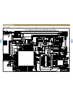
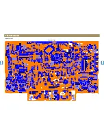
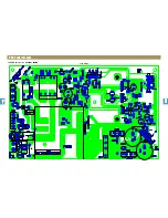
P.C.B Pattern Layout

AMP Section : NC-8809E/NC-8809EK 

<Top View>

1

2

3

4

5
6

7

8

1
2
3
4
5
6
7
8

9

9

Summary of Contents for EKE

Page 1: ...Service Manual Mini Component Sound System 9CD8308000 May 2009...

Page 2: ...T 3 WIRING DIAGRAM 4 BLOCK DIAGRAM 5 SCHEMATIC DIAGRAM 6 FRONT Section FUNCTION Section MP3 CD Section AMP Section POWER Section P C B PATTERN LAYOUT 7 FRONT Section FUNCTION Section MP3 CD Section AM...

Page 3: ...2 Carts and Stands The appliance should be used only with a cart or stand that is recommended by th manufacturer 3 An appliance and cart combination should be moved with care Quick stops excessive for...

Page 4: ...quid Entry Care should be taken so that objects do not fall and liquids are not spilled into the enclosure through openings 16 Damage Requiring Service The appliance should be serviced by qualified se...

Page 5: ...EX2 Check the circuit connected with S1A0071 4PIN And repair Refer to EX5 Normal PWM waveform at S1A0051 10 11 14 15pin Refer to EX12 Relpace components connected with S1A0071 6 7pin 8 9pin 16 17pin...

Page 6: ...es Triangle wave flow to S1A0071 3pin Refer to EX1 S1A0071 6 7pin 8 9pin 16 17pin 18 19pin short 100ohm open Refer to EX10 Normal PWM waveform at S1A0051 10 11 14 15pin Refer to EX12 Replace component...

Page 7: ...Trouble Shooting Guide AMP Flow Chart Test Point and Expected Results Ex1 2 AMP Flow Chart Test Point and Expected Results Ex3 1 2 3 4 5 6 7 8 9 1 2 3 4 5 6 7 8 9...

Page 8: ...Trouble Shooting Guide AMP Flow Chart Test Point and Expected Results Ex4 5 AMP Flow Chart Test Point and Expected Results Ex6 9 1 2 3 4 5 6 7 8 9 1 2 3 4 5 6 7 8 9...

Page 9: ...Trouble Shooting Guide AMP Flow Chart Test Point and Expected Results Ex7 8 AMP Flow Chart Test Point and Expected Results Ex7 8 1 2 3 4 5 6 7 8 9 1 2 3 4 5 6 7 8 9...

Page 10: ...Trouble Shooting Guide AMP Flow Chart Test Point and Expected Results Ex9 AMP Flow Chart Test Point and Expected Results Ex10 13 9 1 2 3 4 5 6 7 8 9 1 2 3 4 5 6 7 8 9...

Page 11: ...Trouble Shooting Guide AMP Flow Chart Test Point and Expected Results Ex11 AMP Flow Chart 1 2 3 4 5 6 7 8 9 1 2 3 4 5 6 7 8 9...

Page 12: ...CD open and disc insertion Refer to 2 Spindle motor rotation Pick up unit return outside inside Laser diode on Focusing operation Read in operation and auto adjustment CD play on Refer to 3 Refer to...

Page 13: ...5927FM 21pin 22pin SP 4 3V SP 4 8V 5 Check SPDO 1 9V IC501 LC786951 41pin 6 Check IC503 BA5927FM 19pin 20pin SL 4 5V SL 4 7V 7 Check CD Board Around IC solder short cold soldering CD open and disc ins...

Page 14: ...39pin 2 Check XC502 12MHZ 3 Check CD Board IC504 Around pin solder short cold soldering 1 Check 9V CN509 of 4pin 2 Check 3 3V IC501 of 59pin 80pin 109pin 124pin 3 Check XC501 16 9344MHZ 4 Check IC503...

Page 15: ...HQ715 HQ716 4 Check IC701 73pin 74pin 75pin 76pin 77pin 78pin no 1 Check CN701 of 7 pin 4V 2 Check IC701 of VCC 17 pin 72 pin 90 pin voltage 3 3V 3 Check VPP voltage 31 9 IC701 of 51pin 4 Check betwee...

Page 16: ...lume Location 3 Check IC352 NJM4558 Power 9V 4pin 9V 8 Pin 4 Check IC352 NJM4558 output 1 7 Pin signal no 1 Check CW702 1pin 3pin input signal 2 Check IC705 3pin 5pin input signal 3 Check IC705 4pin V...

Page 17: ...Pin 6 Check IC AUDIO PROCESSOR IC801 S1A0071_401 7 Check IC FET DRIVER IC802 S1A0051X 8 Check J801 AC cord in VFD display stand_by no 1 Check PT901 2 Check PT992 only PSM 3 IC991 2pin and 4pin voltage...

Page 18: ...Exploded View and Mechanical Parts List 1 2 3 4 5 6 7 8 1 2 3 4 5 6 7 8 9 9...

Page 19: ...H 0 0 6 9 0 4 0 D C 9 P O T R E V O C 6 2 1 S P I H 1 L 7 7 1 4 0 D C 9 L E D I S R E V O C 7 2 1 S P I H 1 R 7 7 1 4 0 D C 9 R E D I S R E V O C 8 2 29 CHASSIS BOTTOM 9CD0612621 SECC T1 0 1 30 BRACK...

Page 20: ...Wiring Diagram 1 2 3 4 5 6 7 8 1 2 3 4 5 6 7 8 9 9 A3 D C B A 3 4 1 2 A B C D 1 2 3 4 A3 D C B A 3 4 1 2 A B C D 1 2 3 4...

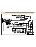
Page 21: ...1 2 3 4 5 6 7 8 1 2 3 4 5 6 7 8 9 9 Title 1 2 3 5 6 7 8 1 2 3 6 7 8 9 9 Block Diagram A3 D C B A 3 4 1 2 A B C D 1 2 3 4 A3 D C B A 3 4 1 2 A B C D 1 2 3 4...

Page 22: ...ONT Section CD_MUTE AD_RESB CLOCK DATA_IN USB_RESB USB_IN MOTOR OPEN_CD CHIP_ENABLE USB_UART_RX USB_CANCEL UP DN_SW OP CL_SW R_CON RESB DATA_OUT USB_MUTE USB ROULETTE_SENSE MOTOR CLOSE_CD TO CD USB_UA...

Page 23: ...LOC X LOC CW403 8809EK CONNECTOR GAME REMARK JW419 JW439 HR447 O X O X O S W GAIN OPTION WAFER WAFER OPTION XG 727 728 7283 NC 8806 7 8 9EK XG 727 728 7283 NC 8806 7 8 9EK 9V SW and UNSW OPTION WAFER...

Page 24: ...LE_M CE587 100 6 3 68K HR616 HR618 0 470 HR612 HC585 0 01uF HC587 0 1uF 0 1uF HC584 VREF 470 HR584 470 HR585 0 1uF HC583 HR581 330 HC581 4700pF 470 HR582 CE581 100 6 3 16 9344 XC501 R_CON NEW CD MECHA...

Page 25: ...9 B1 6 PGND3 5 PGND2 4 B2 2 B1 1 PGND1 3 HEATSINK2 HEATSINK2 2 1 TP19 TEST POINT TP19 TEST POINT 1 HR830 390_1608 HR830 390_1608 TP35 TEST POINT TP35 TEST POINT 1 HC8106 50V X7R 0 022MF K 1608 HC8106...

Page 26: ...9V 38 1V 13 9V XG 728 XG 725 NC 8807 8 XG 725 8 O O JW937 JW938 F902 L902 L901 F901 JW914 OPEN OPEN X O Other 9 0V AC5 6V 31 9V 15 2V NC 8807 8 XG 618UW F902 X CF901 JW913 OPEN F902 1 0 O SW901 ZH 06...

Page 27: ...1 2 3 4 5 6 7 8 1 2 3 4 5 6 7 8 9 9 Title P C B Pattern Layout FRONT Section Top View...

Page 28: ...FRONT Section Bottom View 1 2 3 4 5 6 7 8 1 2 3 4 5 6 7 8 9 9 Title P C B Pattern Layout...

Page 29: ...1 2 3 4 5 6 7 8 1 2 3 4 5 6 7 8 9 9 Title P C B Pattern Layout FUNCTION Section Top View Bottom View...

Page 30: ...Title P C B Pattern Layout MP3 CD Section Top View 1 2 3 4 5 6 7 8 1 2 3 4 5 6 7 8 9 9...

Page 31: ...Title P C B Pattern Layout MP3 CD Section Bottom View 1 2 3 4 5 6 7 8 1 2 3 4 5 6 7 8 9 9...

Page 32: ...P C B Pattern Layout AMP Section NC 8809E NC 8809EK Top View 1 2 3 4 5 6 7 8 1 2 3 4 5 6 7 8 9 9...

Page 33: ...P C B Pattern Layout AMP Section NC 8809E NC 8809EK Bottom View 1 2 3 4 5 6 7 8 1 2 3 4 5 6 7 8 9 9...

Page 34: ...P C B Pattern Layout POWER Section NC 8809E NC 8809EK Top View 1 2 3 4 5 6 7 8 1 2 3 4 5 6 7 8 9 9...
Page 35: ...P C B Pattern Layout POWER Section NC 8809E NC 8809EK Bottom View 1 2 3 4 5 6 7 8 1 2 3 4 5 6 7 8 9 9...

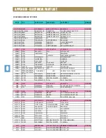
Page 36: ...F RED PI3 LD713 714 715 716 LD717 718 719 720 FRONT VR701 5SH1224375 SW ENCODER RE0123PVB25FINB 1 2 24 PCE FRONT VR702 5SH2830A05 SW ENCODER EVQV5C00315B FRONT XC701 5XE12M000J CRYSTAL QUARTZ 12 000MH...

Page 37: ...412AK X 2 AMP HQ824 825 TEMT2 TR CHIP EMT2 2SA1037AK X 2 AMP L801 802 803 804 5LF150K855 COIL FILTER 15uH TC16B 09 K R A M E R K E 9 0 8 8 C N S A R E W O P B C P 0 0 7 1 A 0 C D C 9 0 0 0 6 1 R E W O...

Reviews: