- EXTERNAL VIEW -
..................................................................................................
..................................................................................................
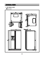
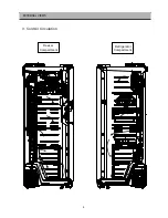
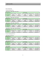
1. External size
2
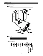
2. Refrigeration cycle
4
..................................................................................................
..................................................................................................
3. Cold air circulation
5
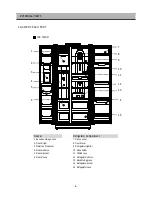
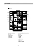
4. Name of each parts
6
- SPECIFICATION -
..................................................................................................
..................................................................................................
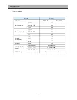
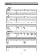
1. Specificatin
8
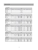
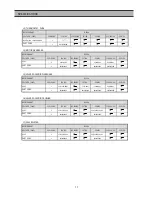
2. Electric parts
9
..................................................................................................
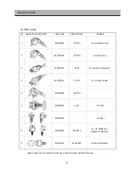
3. Door color code
13
- OPERATION AND FUNCTION -
..................................................................................................
..................................................................................................
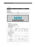
1. Display
14
17
18
20
21
25
27
28
31
32
33
2. Temperature control of FC
..................................................................................................
3. Temperature control of RC
..................................................................................................
..................................................................................................
4. Sleep mode
..................................................................................................
..................................................................................................
23. Automatic icemaker
36
39
24. Dispenser control
5/6. Silent/Control of each mode
..................................................................................................
- DIAGRAM -
..................................................................................................
..................................................................................................
1. Wiring diagram
41
43
2. Circuit wiring diagram
- INSTALLATION GUIDE -
..................................................................................................
..................................................................................................
1. Installation preparation
45
47
2. How to install water line
..................................................................................................
3. Leveling & Adjustment
50
- EXPLODED VIEW-
..................................................................................................
1. FRS-T24DA* Exploded view
51
..................................................................................................
2. FRS-T24DA* Parts List
57
..................................................................................................
3. FRS-T24FA* Exploded view
63
..................................................................................................
4. FRS-T24FA* Parts List
69
7. Defrosting cycle
..................................................................................................
..................................................................................................
8. Defrosting mode
9. Error display
..................................................................................................
10/11. Forced/Initial defrosting
12/13. Buzzer/LCD Background light
14/15/16. Explanation after delivery/Prevention of Comp. restart/Back up function
..................................................................................................
17. Delay function
34
35
35
..................................................................................................
18/19/20. Home bar heater/Control of interior lights/Demo function
21. Reg. of R-sensor off point
..................................................................................................
22. Summary
C O N T E N T S
SAFETY AND PRECAUTION
1) For starters, be sure to check any chances of the leakage of electricity
2) You could handle a part in the vicinity of electricity after unplugging
3) You should put on rubber glovers to prevent an electric shock on operation test
4) Make sure the rated current, voltage, capacity before using an instrument
5) Keep your wet hands away from the metal goods in the freezer compartment not to be frostbitten
6) Be careful not to let water to permeate the electric part in the machine room
Summary of Contents for FRS-T24FA Series
Page 3: ...2 EXTERNAL VIEWS 1 EXTERNAL SIZE...
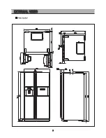
Page 4: ...3 EXTERNAL VIEWS...
Page 6: ...5 3 Cold Air Circulation Freezer Compartment Refrigerator Compartment EXTERNAL VIEWS...
Page 42: ...41 RSCR TYPE 1 WIRING DIAGRAM DIAGRAM...
Page 43: ...42 DIAGRAM CSR TYPE...
Page 44: ...43 DIAGRAM 2 CIRCUIT WIRING DIAGRAM Main PCB...
Page 45: ...44 FRONT PCB DIAGRRAM DIAGRAM...


