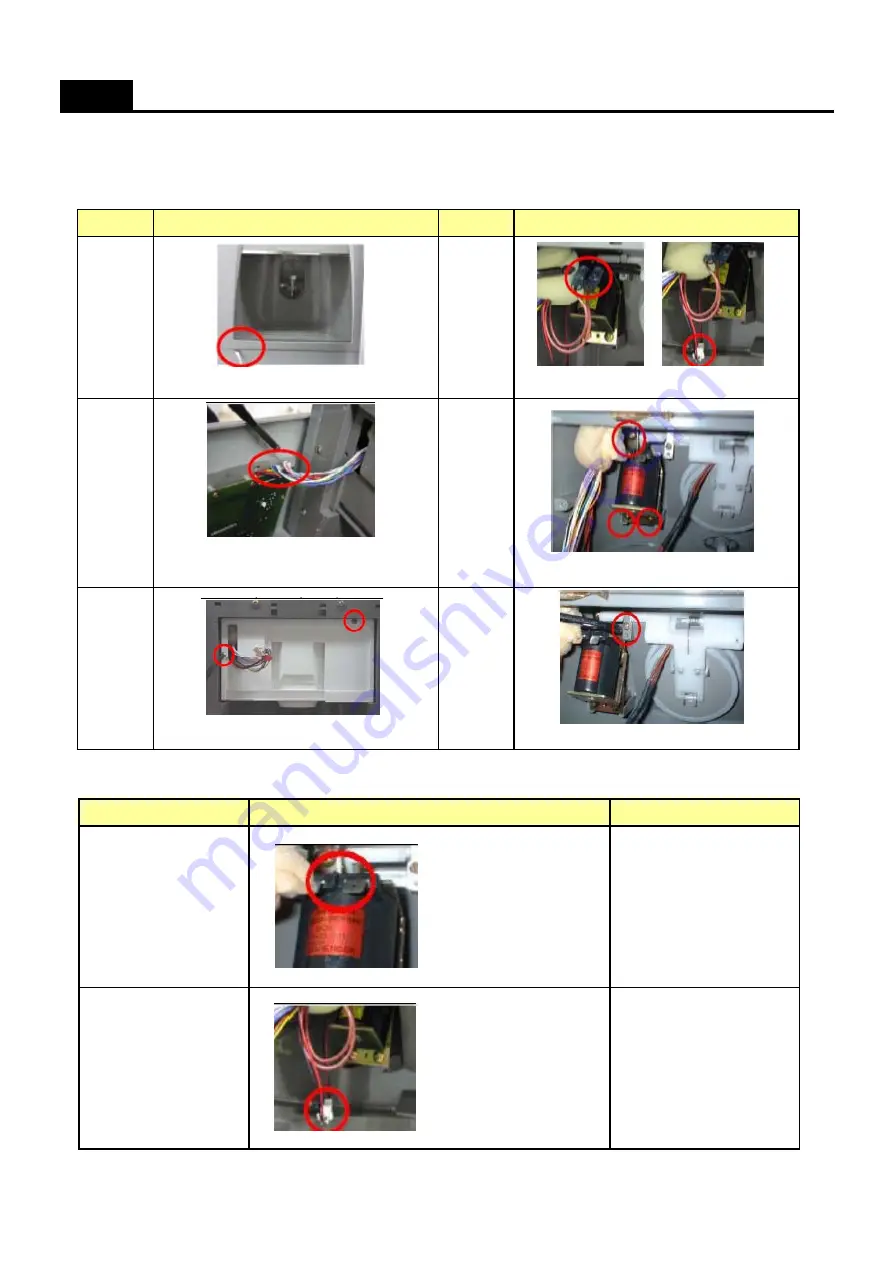
4. Dispenser Solenoid Valve (Dispenser Models Only)
1) Disassembling Procedure (Features are model dependent)
2) How to check Dispenser Solenoid Valve
HOW TO CHECK EACH PART
No
No
5
Procedure
Procedure
Disassemble the Cover dispenser Box As
Disconnect 2 terminals and 2P Wire.
Unscrew and remove Cover Ice Flap.
Unscrew to remove Box Dispenser Ice Shut.
1
4
Unscrew and remove Solenoid Valve.
Separate Front PCB connector.
(Features are model dependent.)
3
6
2
( Good ): 215 Ohm (+-10%)
(193 ~ 236 Ohm)
(Defective): Change the part.
( Good ): 96 Ohm (+-8%)
(88 ~ 104 Ohm)
(Defective): Change the part.
Check the resistance of
both terminals.
Check the resistance of
2 terminals with a Tester.
Flap Heater Assembly
Dispenser Solenoid Valve
Parts
How to Check
Remark
35
Summary of Contents for FRU-541 Series
Page 1: ...Mar 2010 S M No FRSU20IA05...
Page 4: ...2 External Size SPECIFICATIONS 3...
Page 30: ...1 Inner Basic Model 2 Basic Model 3 Dispenser Model WIRING DIAGRAM Refrigerant R 134a Type 29...
Page 31: ...1 Inner Basic Model 2 Basic Model 3 Dispenser Model WIRING DIAGRAM Refrigerant R 600a Type 30...
Page 32: ...1 Inner Basic Model 2 Basic Model 3 Dispenser Model WIRING DIAGRAM for Inverter Compress 31...
Page 55: ...COOLING CYCLE HEAVY REPAIR Brzing Reference Drawings 54...
Page 56: ...Water System for Dispenser Model 55...
Page 57: ...How to install water line Dispenser models only 56...
Page 58: ...How to install water line Dispenser models only 57...


