www.daewoopower.bg
8
EN
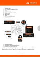
1. IDENTIFICATION OF COMPONENTS
Lorem ipsum
2. PRE-OPERATING PROCEDURE
Inspect all components for damage and to ensure that none are missing. If you require a replace-
ment, do not operate this tool until all parts are present and in proper working order.
Do not modify or create accessories for this equipment. Using modified components may result in
damage and may void the warranty. Contact customer service if you suspect that this equipment
has been tampered with.
2.1 - Engine Oil Check
1. Ensure the Trash Pump is on a level surface.
2. Inspect engine oil
Take out the dipstick and clean it with a dry towel.
Check the oil level by reinserting the oil filler cap without rotating it.
Remove the oil filler cap and examine the oil level. If the oil level is at or below the lower level, refill
the oil to the upper limit mark. (10W30)
Reinsert the oil filler cap and tighten securely.
3. If necessary, add engine oil - Open oil inlet located opposite the recoil starter handle. Remove the
dipstick and pour in the supplied oil with a funnel. Do not operate without oil.
Reservoir can hold maximum 20 fl.oz of 10W30 oil - do not over fill.
Engine oil is a major factor affecting engine performance and service life. Non-detergent or vegeta-
ble oils are not recommended.
2.2 - Fuel Level Check
1. Check the fuel level by opening the tank and visually inspecting.
2. Refuel if level is too low. Tighten the fuel tank cap securely after refilling.
Gasoline is highly flammable and explosive under certain conditions. Refuel in a well-ventilated area
with the engine stopped. Do not smoke or allow open flames or sparks in the area where the Trash
Pump is being refueled or where gasoline is stored. Do not overfill the tank. Be careful not to spill
fuel when refueling. Wipe up any spilled gasoline and let the area dry before starting the engine.
Gasoline substitutes such as gasohol are not recommended. They may be harmful to the fuel
system components.
2.3 - Check the Air Filter
1. Loosen the knob and remove the air filter cover. Remove the air filter element and inspect for
cleanliness.
2. Clean the air filter element with soap and water or solvent. Squeeze dry and then soak in clean
engine oil.
3. Squeeze out all excess oil and reinstall. Replace the element if it is damaged.
Check the air filter according to the maintenance schedule. Always inspect the air filter before using
the Trash Pump. Clean Air Filter every 3 months or after 50hrs of operation according Section 5.4:
Air Filter Service procedure.
2.4 - Hose Connections
1. Insert adapters into each end of the suction and discharge hoses.
2. Attach O-Rings to the adaptors.
3. Tighten the hose clamp around the discharge hose.
4. Insert strainer into the suction hose and tighten the hose clamp around the hose.
5. Insert adapters into the appropiate pump fittings. Avoid sharp bends in the hoses and do not
place heavy objects on top.
3. OPERATION
3.1 - Pump Placement
Placement is an important step in safely operating this product.
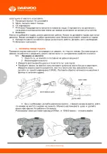
1. Refer to diagram for proper placement instructions.
2. Ensure that the suction head is less than the discharge head.
3. Increasing the discharge head will decrease output.
4. Ensure pump is primed to minimize the suction head.
Suction head is the height to which a pump can raise water on the suction side, measured from the
water level in the sump. Discharge head is the vertical distance between the intake level of the water
pump and the level at which it discharges water freely. Total head is the sum of the suction and
discharge head.
3.2 - Priming Water
Make sure to prime the pump with water prior to operating it. Priming creates a vacuum that helps
to start the flow of water.
1. Unscrew the primer cap and insert the neck of the water container into the opening. Gradually tilt
until the reservoir is full.
2. Tighten the cap back on.
3. In case of dry operation (running the pump without priming), stop the engine immediately and
allow it to cool before following the priming procedure.
Do not operate without priming. Doing so will overheat the engine and result in damage to the
system. Ensure that the priming water does not contain debris.
3.3 - Starting the Trash Pump
RECOIL START METHOD
1. Rotate the fuel valve lever to ON position.
2. If the engine is cold: Push the choke lever to the CLOSE position out to close the choke.
3. Grasp the recoil starter handle and pull it until the engine starts.
4. Push the choke lever to the OPEN position as the engine warms up. The choke is used to provide
the proper mixture when the engine is cold. It can be opened and closed manually by moving the
choke lever to the closed position to enrich the mixture for cold starting.
5. After 5 minutes, slowly push the throttle lever to the OPEN position. Engine RPMs will increase
until engine reaches its stable running speed.
If the engine backfires or does not start repeated attempts, contact customer support and do not
attempt to use the Trash Pump.
3.4 - Stopping the Engine
1. Return the throttle lever to the IDLE position (towards the right)
2. Turn the engine switch to the OFF position
3. Turn the fuel valve to the OFF position
In an emergency, the engine can be quickly stopped by turning the engine switch
to the OFF position.
4. MAINTENANCE
4.1 - Importance of Maintenance
Proper maintenance ensures safe, economical and trouble-free operation. Improper maintenance
may cause the Trash Pump to malfunction and can lead to serious injuries. Contact daewoo Power
Customer Support if you have any maintenance questions.
4.2 - Maintenance Schedule
4.3 - Oil Change and Oil Drainage
Used motor oil can cause skin irritations if left in long-tern contact with skin. Wash hands thoroughly
with soap and water after handling oil.
Do not dispose of used oil in drains or on soil. Local service shops provide environmentally-friendly
disposal methods.
1. Stop the engine and remove oil filler cap.
2. Place a pan under the engine.
3. Remove the oil drain screw and allow the oil to completely drain into the pan.
4. Reinstall drain screw before filling the engine with fresh oil. Do not overfill oil reservoir.
Use a funnel oil reservoir. Use a funnel to prevent spillage.
5. Reinstall the filler cap and tightly fasten it.
4.4 - Air Filter Service
Using gasoline or other flammable solvents can cause a fire or explosion. Do not use these to clean
the air filter. Do not operate this product without an air filter.
1. Unscrew the air filter cover.
2. Remove the filter element and wash with soap and water.
3. Pour a small amount of oil on filter element and squeeze out any excess.
Do not wring the filter element or apply excessive pressure. Smoke may appear if too much oil is left
in the air filter.
4. Reinstall the filter element and cover, ensuring a complete seal around the filter.
4.5 - Spark Plug Service
Do not rinse spark plug in water. Follow guidelines and be careful not to overtighten the spark plug.
Tighten ½ turn when installing a new spark plug.
Tighten ¼ turn when re-installing an old spark plug.
1. Disconnect and remove the spark plug using a wrench.
2. Inspect the spark plug and clean any dirt from the electrodes with a wire brush. If electrodes are
worn or show signs of wear, replace spark plug.
3. Measure the electrode gap with a spark plug gauge and adjust as necessary by bending the side
electrodes. Ensure that the gap is between 0.7 and 0.9mm
4. Reinsert the plug carefully. Tighten with a spark plug wrench.
4.6 - Fuel Sediment Cup Service
1. Switch fuel valve to the OFF position.
2. Unscrew the sediment cup using a wrench and remove the O-ring.
3. Wash the cup and O-ring in a non-flammable solvent and dry thoroughly.
4. Place the O-ring in the fuel valve, then attach sediment cup. Tighten securely.
5. Switch the fuel valve to the ON position and check for leaks. Replace O-ring if leakage occurs.
4.7 - Fuel Drainage
1. Place container underneath the while removing the drain screw from the carburetor.
2. Turn the fuel valve to ON and slowly remove the fuel drain screw.
3. Allow fuel to drain fully and reinsert the screw.
4.8 - Impeller Cleaning
Impeller cleaning is important when storing pump for long periods of time. It is also advisable as
part of regular maintenance checks.
QUICK METHOD
1. Fill pump with fresh water through primer opening.
2. Start pump and allow it to run for up to 8 minutes or until water evaporates upon contact with
engine block.
3. Drain water through pump drain outlet.
4. Flush pump with clean water (puring it through primer opening).
5. Reinsert drain screw.
INTENSIVE CLEANING
1. Remove / unscrew all 6 pump casing bolts from the pump.
2. Carefully remove the outside casing, exposing the impeller.
3. Clean impeller using regular soap and water, if necessary use a light scrubbing tool
to remove debris.
4. Reinstall casing on trash pump and fasten all bolts.
When reinstalling the casing, ensure that the rubber seal is properly secure all around the perimeter
of the opening.
4.9 - Transportation
Engine and exhaust can become hot. Avoid contact due to risk of burns and fires. Allow engine to
cool before transporting unit. Do not drop or strike the pump during transport. Avoid placing heavy
objects on the frame or gas tank.
• Make sure engine and fuel valve are in the OFF positions
• Keep the unit level to prevent spillage.
• Place pump on a solid, level surface and secure it to prevent movement during transport
4.10 - Storage
Do not store close to sources of heat, flames or sparks. Do not store in extremely humid or dusty
areas. Do not store with gasoline still inside carburator or gas tank.
1. Clean the impeller and drain water out
2. Drain gasoline from tank and carburator
3. Change engine oil
4. Slide fuel valve to OFF position
5. Place pump in an appropriate storage area at temperatures above 32°F
6. Cover inlet and outlet ports
7. Cover unit to protect it from dust
4.11 - External Parts Cleaning
Keeping the external parts clean can prevent debris build-up and ensure easy access during main-
tenance. Do not use a pressure washer to clean this product. Delicate electrical components may
be damaged.
1. Place unit in a well-lit area
2. Use a grease-removing solvent (non-flammable) and a cloth to clean areas around the gas tank
and oil ports.
3. Use a soft, damp cloth to clean off remaining residue and debris.
4. Allow unit to dry before using it.
5. TROUBLESHOOTING
Common issues can be fixed by following the instructions in this guide. If the unit will not function
after following these instructions, contact technical support before attempting to use or repair the
product.
6. SPECIFICATIONS
6
4.
Summary of Contents for GAET50
Page 18: ...www daewoopower bg 18 BG 3 1 1 1 1 5 2 z z z z z z z z z z z z z z...
Page 20: ...www daewoopower bg 20 BG 5 4 5 6 7 8 9 10 3 3 1 1 2 10W30 3 590 10W30 y y...
Page 21: ...www daewoopower bg 21 BG 3 2 1 2 3 3 1 2 3 3 50 5 4 3 4 1 2 3 4 5...
Page 22: ...www daewoopower bg 22 BG 7 4 4 1 1 2 3 4 4 2 1 2 3...
Page 25: ...www daewoopower bg 25 BG x x 5 3 1 2 3 4 5 5 4 1 2 3 4...
Page 26: ...www daewoopower bg 26 BG 5 5 1 2 3 0 7 0 9 mm 4 5 6 1 OFF 2 3 4 5 ON...
Page 27: ...www daewoopower bg 27 BG 12 5 7 1 2 ON 3 5 8 1 2 8 3 4 5 1 6 2 3 4 5 9...
Page 36: ...www daewoopower bg 36 BG 24 6 6 12 6...
Page 37: ...www daewoopower bg 37 BG 1 1 2022 6 6...
Page 38: ...ZZZ GDHZRRSRZHU EJ...


