12
6. Trouble Shooting Guide
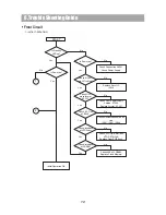
START
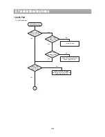
1. INITIAL OPERATING
Is Standby
LED on?
No
Initial Operation OK.
Check if IC501
pin 207 is high?
Yes
Check OSC
waveform of
XC501.
Yes
Check I2C Line
of IC504.
Yes
Yes
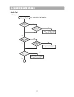
Check interface
of VFD Driver
Yes
Is Power on?
Check Connection CN701.
Check Power Supply.
No
No
No
No
No
Yes
Replace Reset IC.
IC508.
Check DVD Power Supply
Section, PT902.
Replace Crystal, XC501.
Check Devices connected I2C
Line.
IC201, IC401, IC408.
Check VFD Data Interface.
VFD_DATA/CLK.
Replace Front PCB Ass’y.
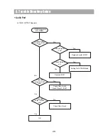
Check interface
of SDRAM
No
Check CLK of SDRAM.
Replace Flash Memory.
Is Power on?
1
No
Yes
2
Yes
Front Circuit
Summary of Contents for HC-4130X
Page 34: ...8 Internal Block Diagram of ICs 74HC00 32 74HC14 74HC374 74HCU04...
Page 35: ...8 Internal Block Diagram of ICs AK4117 AK5365 33 BA6287F BA7660FS...
Page 36: ...8 Internal Block Diagram of ICs CS4360 34 ES6629FD ES6698FD...
Page 37: ...8 Internal Block Diagram of ICs FAN8024DB 35 LA7952 M29W800DB LD1117A...
Page 38: ...STA505 8 Internal Block Diagram of ICs 36 PT6315...
Page 39: ...8 Internal Block Diagram of ICs STA308A 37...
Page 40: ...9 Block Diagram Main Block 38 HC 4130...
Page 41: ...9 Block Diagram 39 SMPS Block HC 4130...
Page 42: ...10 Wiring Diagram HC 4130 40...
Page 44: ...11 Schematic Diagram DVD RF Section 42 HC 4130...
Page 45: ...11 Schematic Diagram HC 4150 VIDEO ANALOG AUDIO SECTION Video Analog Audio Section 43 HC 4130...
Page 46: ...11 Schematic Diagram HC 4130 DDX ECTION DDX Section HC 4130 44...
Page 47: ...HC 4130 PWM MP SECTION 11 Schematic Diagram PWM Amp Section HC 4130 45...
Page 48: ...11 Schematic Diagram Front Section HC 4130 46...
Page 49: ...11 Schematic Diagram SMPS Section 47 HC 4130...
Page 50: ...12 Exploded View and Mechanical Parts List 48 HC 4130...
Page 51: ...12 Exploded View and Mechanical Parts List 49 HC 4130...


