17
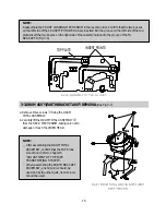
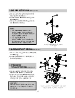
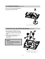
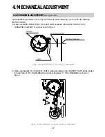
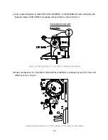
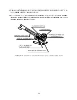
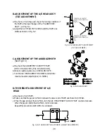
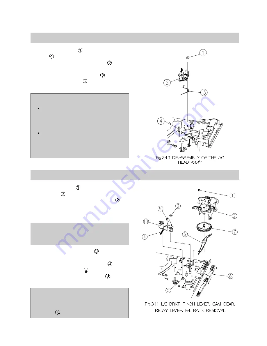
3-5. A/C HEAD ASS'Y REMOVAL
(See Fig.3-10)
a. Remove one nut hex
from the A/C HEAD
POST
of the MAINBASE.
b. Remove the A/C HEAD ASSEMBLY
from
the MAINBASE.
c. Remove the A/C HEAD SPRING
from the
A/C HEAD ASSEMBLY
.
NOTE:
After reassembling, adjust the TAPE
TRANSPORTING SYSTEM refering to
chapter 5 "ADJUSTMENT OF THE TAPE
TRANSPORTING SYSTEM".
After adjusting the TAPE
TRANSPORTING SYSTEM, spread the
A/C HEAD/NUT, AZIMUTH SCREW, and
TILT SCREW with LOCKING PAINT.
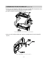
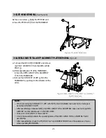
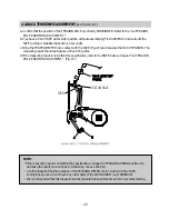
3-6. L/C BRACKET ASS'Y REMOVAL
(See Fig.3-11)
a. Remove one screw
from the L/C BRACKET
ASSEMBLY
.
b. Remove the L/C BRACKET ASSEMBLY
from the MAINBASE.
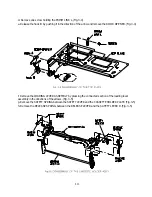
3-7. PINCH LEVER
TOTAL ASS'Y REMOVAL
(See Fig.3-11)
a. Remove one POLY WASHER
from the
PINCH LEVER POST of the MAINBASE.
b. Unhook the PINCH LEVER SPRING
from
the hook of MAINBASE
and remove the
PINCH LEVER TOTAL ASSEMBLY
.
CAUTION:
Take care not to coat GREASE, OIL or other
substances on the surface of the PINCH
ROLLER
.
Summary of Contents for K30
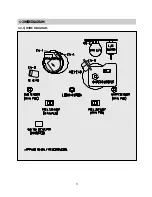
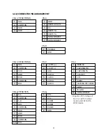
Page 4: ...3 1 2 1 WIRE DIAGRAM 1 2WIREDIAGRAM ...
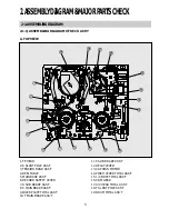
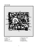
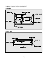
Page 8: ...7 2 1 2 PARTS LOCATION OF FRONT LOADING ASS Y A TOP VIEW B FRONT VIEW ...
Page 38: ...37 6 EXPLODED VIEW AND PARTS LIST 6 1 EXPLODED VIEW OF DECK ASS Y TOP VIEW ...
Page 39: ...38 6 2 EXPLODEDVIEWOFDECKASS Y BOTTOMVIEW ...
Page 40: ...39 6 3 EXPLODEDVIEWOFF LASS Y ...
Page 41: ...40 D0040 D0020 D0050 D0010 D0080 D0090 D0060 D0070 D0040 ...

