background image

26

• Disconnect the oven from the power supply.
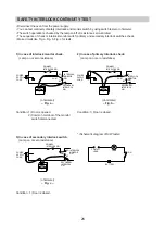
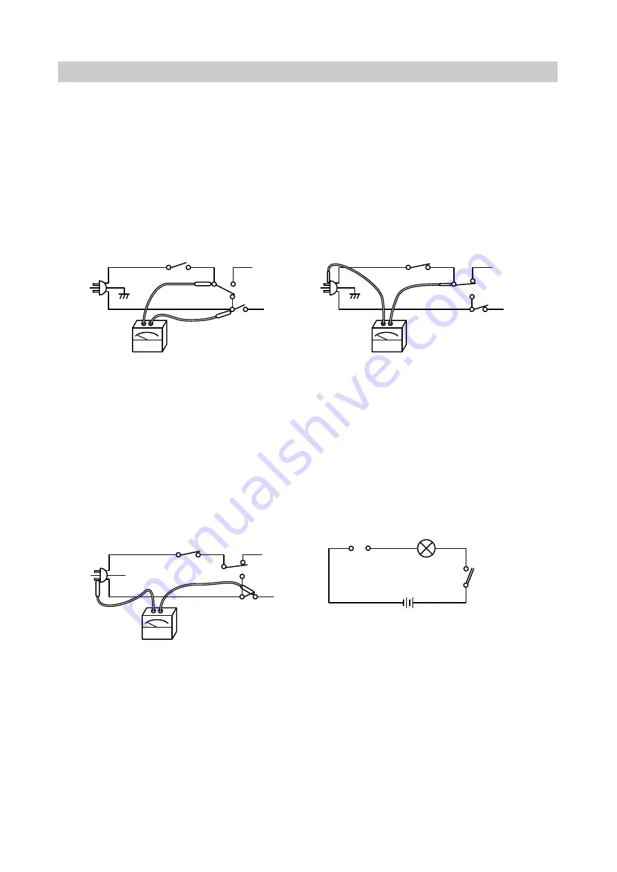
• You can test continuity of safety interlocks and monitor switch by using switch tester or ohmmeter.
• The switch operation is checked by the lamp on/off of resistance zero/unlimited.
• The sequence of check is interlock monitor switch; primary and secondary interlock switches check.
• Make circuits like Fig. a, Fig. b, Fig. c for tests.

SAFETY INTERLOCK CONTINUITY TEST

1) In case of interlock monitor check.

(Lamp on or zero resistance)

(ohmmeter)

– Fig. a –

Condition: 1) Door is opened.

2) Common terminal of the monitor 

switch disconnected.

3) In case of secondary interlock switch.

(Lamp on or zero resistance)

(ohmmeter)

– Fig. c –

Condition : 1) Door is closed.

2) In case of primary interlock check.

(Lamp on or zero resistance)

(ohmmeter)

– Fig. b –

Condition: 1) Door is closed.

* (Schematic diagram of S/W tester)

POWER
SUPPLY
CORD

POWER
SUPPLY
CORD

PRIMARY
INTERLOCK S/W

PRIMARY
INTERLOCK S/W

NO

NO

COM

COM

NC

NC

INTERLOCK
MONITOR
S/W

INTERLOCK
MONITOR
S/W

SECONDARY
INTERLOCK
S/W

SECONDARY
INTERLOCK
S/W

POWER
SUPPLY
CORD

PRIMARY
INTERLOCK S/W

NO

COM

NC

INTERLOCK
MONITOR
S/W

SECONDARY
INTERLOCK
S/W

CONTACT

LEAD

LAMP

S/W

BATTERY

Summary of Contents for KOG-3805

Page 1: ...Service Manual Microwave Oven Model KOG 3805 DAEWOO ELECTRONICS CO LTD ...

Page 2: ...cavity for proper alignment integrity and connection d Any defective or misadjusted components in the interlock monitor door seal and microwave generation and transmission systems shall be repaired replaced or adjusted by procedures described in this manual before the oven is released to the owner e A microwave leakage check to verify compliance with the Federal Performance Standard should be perf...

Page 3: ... make repairs 1 A broken door hinge 2 A broken door viewing screen 3 A broken front panel oven cavity 4 A loosened door lock 5 A broken door lock The door seal area and oven cavity surface be kept clean No grease soil or spatter should be allowed to build up on these surfaces or inside the oven DO NOT ATTEMPT TO OPERATE THIS APPLIANCE WITH THE DOOR OPEN The microwave oven has concealed switches to...

Page 4: ...L 1050 W COMBINATION 2350 W MICROWAVE ENERGY OUTPUT 900 W MICROWAVE FREQUENCY 2450 MHz OUTSIDE DIMENSIONS WXHXD 495X382X289 mm CAVITY DIMENSIONS WXHXD 320X330X225mm NET WEIGHT 16 5 Kg TIMER 35 min DUAL SPEED FUNCTION SELECTIONS MICROWAVE GRILL COMBINATION MICROWAVE POWER LEVELS 3 LEVELS Specifications subject to change without notice 289 ...

Page 5: ... of special heat resistant glass Food in a proper receptacle is placed on this tray for cooking 7 Roller Guide This must always be used for cooking together with the glass cooking tray 8 Coupler this fits over the shaft in the center of the oven s cavity floor This is to remain in the oven for all cooking 9 Knob V P C Used to select a microwave power level 0 Knob Timer Used in setting cooking time...

Page 6: ...about 1 0 meters long Do not use an extension cord If the supply cord is damaged it must be replaced by the manufacturer or its service agent or a similarly qualified person in order to avoid a hazard INSTALLATION 6 Examine the oven after unpacking for any damage such as Dents A misaligned door Broken door A dents in cavity If any of the above are visable do not install this oven CAUTION Do not un...

Page 7: ...oking cycle by only turning the timer knob Do not let the timer continue to operate after removing food 7 NOTE When using the GRILL or COMBI mode Do not open the door so often the temperature inside the oven decrease and the cooking may not complete in setting time Never touch the oven window and metal interior of the oven when taking food in and out because of the temperature inside the oven and ...

Page 8: ...d immediately before the water is added to the vessel After addition of the water to the vessel the load is immediately placed on the center of the shelf which is in the lowest normal position 4 Microwave power is switched on 5 Heating time should be exactly 47 seconds Heating time is measured while the microwave generator is operating at full power The filament heat up time for magnetrons is not ...

Page 9: ... Place it at the center of the tray and set it in a cavity D Close the door and operate the oven E Measure the leakage by using microwave energy survery meter with dual ranges set to 2450 MHz Measured radiation leakage must not exceed the values prescribed below Leakage for a fully assembled oven with door normally closed must be less than 4mW cm2 When measuring the leakage always use the 2 in 5cm...

Page 10: ...10 WIRING DIAGRAM SLOW ACTING RELAY ...

Page 11: ...11 WIRING DIAGRAM ...

Page 12: ...ltae transformer and this secondary voltage is increased by the action of the diode and the charging of the high voltage capacitor This resultant D C voltage is then applied to the anode of the magnetron As shown in Fig 2 the first half cycle of the high voltage produces in the high voltage transformer secondary charges the high voltage capacitor Current flow is in the direction of the dotted line...

Page 13: ...to the high voltage transformer to stop microwave oscillation Fan motor timer motor and turntable motor stop rotating Oven lamp turn off As soon as the door is opened monitor switch close NC to create the short circuit If the contacts of primary interlock switch and secondary interlock switch are both malfunction the 15A fuse blows open due to the large current surge caused by monitor switch activ...

Page 14: ...repair work 2 Warning about the electric charge in the high voltage capacitor For about 30 seconds after the operation stopped and electric charge remains in the high voltage capacitor When replacing or checking parts short between oven chassis and the negative high terminal of the high voltage capacitor by using a properly insulted screw driver to discharge 4 When the 15A fuse is blown out due to...

Page 15: ...ge top 2 Remove the stopper hinge top 2 and door assembly 3 from top plate of cavity 3 Remove the stopper hinge top 2 from door assembly 4 Reverse the above for reassembly taking care to replace fixing glue 3 To remove door parts NOTE After replacing the door preform a check of correct alignment with the hinge and cavity front face 1 3 2 6 3 Door Plate 2 1 4 5 ...

Page 16: ...1 Loosen three screws on bottom hinge and then the door to contact the door seal to oven front surface 2 Tighten three screws 3 To reduce gap locatated on part C See Fig A 1 Loosen a screw on the interlock switch assembly located at the bottom of the oven body 2 Draw the interlock switch assembly inward as possible to engage with hook on the door bottom 3 Tighten a screw 4 To reduce gap located on...

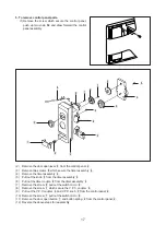
Page 17: ...mbly r 5 Pull out the knob e from the timer assembly r 6 Pull out the timer couple w from the timer assembly r 7 Remove the screw 9 pull out the switch micro 8 8 Remove the screw q which secure the V P C coupler 0 9 Pull out the V P C coupler 0 and V P C knob 3 from the control panel 4 10 Remove the screw 7 pull out the switch micro 6 11 Remove the door open button 1 and button spring 2 from the c...

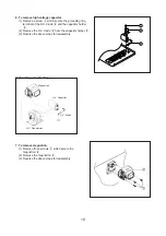
Page 18: ...itor holder 3 2 Remove the H V diode 2 from the capacitor holder 3 3 Reverse the above steps for reassembly High voltage circuit wiring 7 To remove magnetron 1 Remove three screws 1 which secure the magnetron 2 2 Remove the magnetron 2 3 Reverse the above steps for reassembly 1 3 2 Magnetron H V Capacitor H V Transformer H V Diode ...

Page 19: ...H V transformer 2 2 Remove the transformer 2 3 Reverse the above steps for reassembly CAUTION Never install the magnetron without the metallic gasket plate which is packed with each magnetron to prevent microwave leakage Whenever repair work is carried out on magnetron check the microwave leakage It shall not exceed 4mW cm2 for a fully assembled oven with door normally cosed Magnetron antenna Meta...

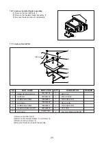
Page 20: ... 3 4 5 6 7 3513301100 3512801700 7002500613 7392500008 7002400413 3515000700 7S627W50X1 1 1 1 1 2 2 2 SPP T0 8 230V 1000W TRS 5X6 MFCR 6N 2 5 SUS TRS 4X4 MFCR C3771BD FLG NUT M5X0 8P MFZN INSULATOR HEATER HEATER SCREW MACHINE NUT HEX SCREW MACHINE SPACER INSULATOR I NUT HEX 1 Remove the HEX Nut 4 2 Remove the Insulator Heater 1 and Heater 2 3 Remove the two screws 5 4 Reverse the above steps for r...

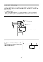
Page 21: ...ed the hook locks the oven door If the door is not closed properly the oven will not operate When the door is closed the hook pushes the button of the micro switch Then the button of the primary interlock switch bring it under on condition ADJUSTMENT 1 When the door is closed the switch button is pushed by the hook The movement of the switch button should exceed 1 2mm measured at the top of the bu...

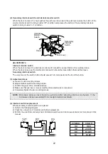
Page 22: ...the two mounting screws b Adjust interlock switch assembly position c Confirm the gap 1 2mm described above d Make sure that push lever moves smoothly after adjustments is completed e Completely tighten the two mounting screws 4 Interlock switch resplacement Whenever safety interlock switch are replaced 1 Refer to the following diagram 2 Check the connection of monitor switch after replacement 3 P...

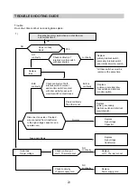
Page 23: ...terlock switch secondary interlock switch and interlock monitor switch All these switches must be replace at the same time Replace H V T Thermal cut out Outlet has Proper voltage Check continuity of H V T Thermal cut out Check continuity of power supply cord Replace high voltage transformer Replace high voltage Capacitor Replace primary secondary interlock switch and interlock monitor switch Repla...

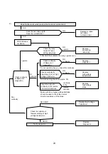
Page 24: ...the contacts of a relay operate oven Normal reading should be approx 0Ω Meter with 6V or higher voltage batteries should be used to check the normal direction resistance of the diode NO GOOD Poor continuity Check the isolation of filament winding of high voltage transformer Faulty magnetron GOOD NO Replace or repair oven lamp turntable motor NO continuity NO continuity continuity in the reverse di...

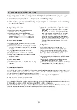
Page 25: ...adings should be as follows Secondary winding Approx 120Ω 10 Filament winding Approx 0Ω Primary winding Approx 0Ω 2 High voltage capacitor A Check continuity of capacitor with meter on the highest OHM scale B A normal capacitor will show continuity for a short time and then indicate 9MΩ once the capacitor is charged C A shorted capacitor will show continuous continuity D An open capacitor will sho...

Page 26: ...nce ohmmeter Fig a Condition 1 Door is opened 2 Common terminal of the monitor switch disconnected 3 In case of secondary interlock switch Lamp on or zero resistance ohmmeter Fig c Condition 1 Door is closed 2 In case of primary interlock check Lamp on or zero resistance ohmmeter Fig b Condition 1 Door is closed Schematic diagram of S W tester POWER SUPPLY CORD POWER SUPPLY CORD PRIMARY INTERLOCK ...

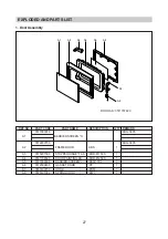
Page 27: ...3517003010 KOG 3805 A1 BARRIER SCREEN O 3512202700 KOG 3805 A2 FRAME DOOR ABS 1 A3 3515201500 STOPPER HINGE T AS KOR 61150S 1 A4 3511706520 DOOR PAINTING AS KOR 81250S 1 A5 3517002900 BARRIER SCREEN I PETP T0 1 1 A6 3512300400 GASKET DOOR PP 1 A7 3513100700 HOOK POM 1 A8 3515101300 SPRING HOOK PW1 1 DOOR AS 3511707420 ...

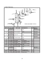
Page 28: ...CREW TAPPING T2S PAN 3X15 MFZN 1 B8 4415A17352 SW MICRO VP 533A OF 1 B9 7121301511 SCREW TAPPING T2S PAN 3X15 MFZN 1 B10 3517400500 COUPLER VPC KNOB POM 1 B11 7122401211 SCREW TAPPING T2S TRS 4X12 MFZN 1 B12 3517400400 COUPLER TIMER POM 1 3513402510 KOG 3805 B13 KNOB ABS 1 B14 3518203800 TIMER KN35MKD 2EE P 1 B15 7122401211 SCREW TAPPING T2S TRS 4X12 MFZN 2 B16 3512764200 HARNESS TIMER KOG 36150S ...

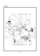
Page 29: ...29 3 Main Unit ...

Page 30: ... 3 F22 SCREW TAPPING 7S312X40A1 T1 TRS 4X10 SE MFZN 2 F23 SCREW MATCHINE 7601400811 PAN 4X8 PW MFZN 2 F24 COVER B 3511402500 SBHG T0 8 1 F25 MOTOR SHADED POLE 3963512100 MW10CA R01 1 F26 FAN 3511800300 PP 30 GLASS 1 F27 SCREW TAPTITE 7272400811 TT3 TRS 4X8 MFZN 1 F28 HOLDER HV CAPACITOR 3513001900 SECC T0 8 1 F29 CAPACITOR H V 4415T66300 2100VAC 0 98uF 1 F30 DIODE H V 4416V24000 HVR 1X 32B 1 F31 T...

Reviews: