background image

47

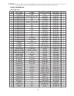
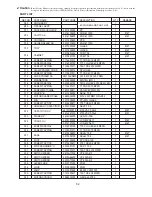
1) PCB PART LIST

5. P.C.B LOCATION NO.

NO

PART NAME

SYMBOL

SPECIFICATION

PARTCODE

Q’TY

1

PCB MAIN

M156

M156

3514313851

1

2

R CARBON FILEM

R6, R9, R10, R12, R17

1/4W 1K

J

RD-4Z102J-

5

3

R CARBON FILEM

R13

1/4W 100

J

RD-4Z101J-

1

4

R CARBON FILEM

R27

1/4W 2K

J

RD-4Z202J-

1

5

R CARBON FILEM

R8, R21, R23, R24, R26

1/4W 4.7

J

RD-4Z472J-

5

6

R CARBON FILEM

R7

1/4W 100K

J

RD-4Z104J-

1

7

R CARBON FILEM

R22

1/6W 1M

J

RD-4Z202J-

1

8

R CARBON FILEM

R5

1/6W 1M

J

RD-AZ105J-

1

9

R CARBON FILEM

R1, R2

1/6W 1K

J

RD-AZ101J-

2

10

R CARBON FILEM

R3

1/6W 1K

J

RD-AZ103J-

1

11

R CARBON FILEM

R4

1/6W 10K

J

RD-AZ103J-

1

12

R CARBON FILEM

R11

1/6W 20K

J

RD-AZ203J-

1

13

R CARBON FILEM

R19, R20

1/2W 6.8K

J

RD-2Z689JS

2

14

R CARBON FILEM

R16, R18, R25

1/2W 470K

J

RD-2Z471JS

3

16

R CARBON FILEM

R14

1/2W 100

J

RD-2Z101JS

1

17

C CERAMIC

C1~C5, C7~C9

50V 0.1uF Z

CCKF1H473Z

8

18

C CERAMIC

C6

50V 0.047uF Z

CCKF1H104Z

1

19

C ARRRAY

CA1

50V 1000PF(5P)

CN4XB-102M

1

20

DIODE ZENER

D1~D5, D10

1N4148

DZN4148-

6

21

DIODE RECTIFIER

D8, D9, D11~D14

1N4002A

DZN4002A-

6

22

DIODE SWITCHING

D6

1N4148M

DZN4148M-

1

23

DIODE ZENER

ZD1, ZD5

MTZ3.9B

DZTZ3R9B-

2

24

DIODE ZENER

ZD2

MTZ5.6B

DZTZ5R6B-

1

25

DIODE ZENER

ZD3, ZD4

MTZ24B

DZTZ5R6B-

2

26

TR DIGITAL

Q1, Q2, Q5

DTA114ES

TDTA114ES-

3

27

TR DIGITAL

Q6, Q11, Q12

KTRA106M

TZRA106M-

3

28

TRANSISTOR

Q3, Q4, Q8

KTA1270Y

TZTA1270Y-

3

29

TRANSISTOR

Q7

KTA1273Y

TZTA1273Y-

1

30

C ELECTRO

EC2, EC4

RS 50V 10uF

CEXE1H100A

2

31

C ELECTRO

EC1

RS 250V 100uF

CEXE1E101A

1

32

C ELECTRO

EC3, EC6

RSS 50V 220uF

CEXF1H221V

2

33

C ELECTRO

EC5

RSS 50V 1000uF

CEXF1H102V

1

34

CONNECTOR

CN1

YW396-02V

3519150520

1

35

CONNECTOR

CN2

HLEM15S-1

4CW215SBD0

1

36

CONNECTOR

CN3

YW396-05AV

3519150510

1

37

WIRE FLAT

1.25X15X90XC

WSJ-159007

1

38

IC MICOM

IC1

TMP47C862AN-GC17

13GSR816T-

1

39

RESONATOR

CR1

KBR-40MKSTF

5PKBR40MKS

1

40

BUZZER

BZ1

MB-20K

3515600100

1

✔ 

Caution:

In this Service Manual, some parts can be changed for improving, their performance without notice in the parts list. So, if you need the

latest parts information, please refer to PPL(Parts Price List) in Service information Center(http://svc.dwe.co.kr)

Summary of Contents for KOR-616T0P

Page 1: ...ELECTRONICS CO LTD Caution In this Manual some parts can be changed for improving their performance without notice in the parts list So if you need the latest parts information please refer to PPL Pa...

Page 2: ...e interlock monitor door seal and microwave generation and transmission systems shall be repaired replaced or adjusted by procedures described in this manual before the oven is released to the owner e...

Page 3: ...ase soil or spatter should be allowed to build up on these surfaces or inside the oven DO NOT ATTEMPT TO OPERATE THIS APPLIANCE WITH THE DOOR OPEN The microwave oven has concealed switches to make sur...

Page 4: ...79 mm CAVITY DIMENSIONS W x H x D 320x 225 x 330 mm 290x 200 x 290 mm NET WEIGHT APPROX 15 0Kg APPROX 13 5Kg TIMER 60 min 00 sec POWER SELECTIONS 5 LEVELS 495 409 289 Stop Defrost 1 2 Weight Quantity...

Page 5: ...k system 6 Door viewing screen Allows viewing of food The screen is designed so that light can pass through but not the microwaves 7 Glass cooking tray Made of special heat resistant glass Food in a p...

Page 6: ...maged must be repaired with cable of same type Such a cable can be purchased from DAEWOO and must be installed by a Qualified Person Examine the oven after unpacking for any damage such as A misaligne...

Page 7: ...he START pad is touched and the oven does not operate check the area between the door and door seal for obstructions and make sure the door is closed securely The oven will not start cooking until the...

Page 8: ...ugged the clock will have to be reset for the proper time Once power is restored or oven is plugged in the display will show 0 00 To reset the time of day repeat the steps given below To check the tim...

Page 9: ...e For example 20 minutes 20 00 will show in the display Time 3 Press button The TIME DEFROST indicator light will start blinking to show the oven is in TIME DEFROST mode Time NOTE During the defrostin...

Page 10: ...ator light will start blinking to show the oven is in WEIGHT DEFROST mode Weight NOTE During the defrosting operation turn over the food after buzzer sound for completed defrosting NOTE This digital w...

Page 11: ...CROWAVE mode Stage 1 NOTE To insure the best microwave and defrost results be sure to start with a cool oven Let the oven cool 15 20minutes with the door slightly open Power levels are 900W 700W 500W...

Page 12: ...how in the display 1 Stage 3 Press POWER button By repeatedly pressing this button you can also select other power levels For example KOR 616T The STAGE2 indicator light will light The WATT indicator...

Page 13: ...e end of stage 1 the oven will beep and start the second stage 2 The STAGE1 indicator light will go off and the STAGE2 indicator light starts blinking The display counts down the time to show you how...

Page 14: ...esired cooking quantity Auto cook 5 Select the desired cooking quantity For example 3 350g 3 will show in the display Auto cook 3 If you want to select other menu press AUTO COOK button until display...

Page 15: ...l Knob until display you desired 8 Buzzer will sound at the end of the cooking time The indicator light will go off The display panel will return to the time of day The oven light will turn off and th...

Page 16: ...ll indicators are lighted setted function Indicator of operating function is blinking SPEEDY COOK 1 min CHILD SAFTY LOCK SETTING THE CONTROL NOTE This key is increased from 30 seconds to 5 minutes If...

Page 17: ...ods rather than to over cook them If a range of times is stated in a recipe cook the minimun suggested time check for doneness and then cook slightly longer if necessary NOTE Oven stops operating when...

Page 18: ...cks the oven door If the door is not closed properly the oven will not operate When the door is closed the hook pushes the button of the micro switch Then the button of the primary interlock switch br...

Page 19: ...fer to the following diagram 2 Check the connection of monitor switch after replacement 3 Perform the electrical continuity check of interlock switches and microwave emission test mentioned in this ma...

Page 20: ...aximum material thickness of 3 mm and an outside diameter of approximately 190 mm 3 The oven and the empty vessel are at ambient temperature prior to the start of the test The initial temperature of t...

Page 21: ...with dual ranges set to 2 450 MHz Measured radiation leakage must not exceed the values prescribed below Leakage for a fully assembled oven with door normally closed must be less than 4mW cm2 When me...

Page 22: ...ols the magnetron by blowing the air coming from the intake on the rear plate hole 3 The oven lamp light the inside of the oven 4 Indicator light turns on to indicate function operation Cooking time s...

Page 23: ...icrowave oven from power level 1 to 5 100 power One complete ON and OFF cycle of the RELAY 1 is 29 seconds The relation between indications on the control panel and the output of the microwave oven is...

Page 24: ...pen the display stops counting down 3 Fan motor and turn table stop rotating 4 The oven lamp turns off 5 As soon as the door is opened the interlock monitor switch contacts close and creats the short...

Page 25: ...e electric charge in the high voltage capacitor For about 30 seconds after the operation stopped and electric charge remains in the high voltage capacitor When replacing or checking parts short betwee...

Page 26: ...2 and door assembly 3 from top plate of cavity 3 Remove the stopper hinge top 2 from door assembly 4 Reverse the above for reassembly taking care to replace fixing glue 3 To remove door parts DISASSE...

Page 27: ...hinge stopper and then the door to contact the door seal to oven front surface 2 Tighten three screws 3 To reduce gap located on part C See Fig A 1 Loosen a screw on the interlock switch assembly loc...

Page 28: ...y B10 4 Remove the PCB ass y B10 from the control panel B02 5 Remove the button cook B04 the button auto cook B09 the button start B03 and the button function B08 from the control panel B02 6 Remove...

Page 29: ...or holder 3 2 Remove the H V diode 2 from the capacitor holder 3 3 Remove the above steps for reassembly High voltage circuit wiring 7 To remove magnetron 1 Remove three screws 1 which secure the magn...

Page 30: ...H V transformer 2 2 Remove the transformer 2 3 Reverse the above steps for reassembly 5 4 2 1 3 1 Magnetron antenna Metallic gasket plate Cooling fin Magnetron Filament terminal 2 1 Wave guide Magnet...

Page 31: ...numbers is in the display 3 One or more digits in the display are not on when they should be 4 Display indicates a number different from one setted For example when 5 00 setted 3 00 appears in the di...

Page 32: ...ontinuity Malfunction of interlock switch Check continuity of primary interlock switch contact with door partially open unit interlock monitor switch contact close COM NC close Shorted contacts of pri...

Page 33: ...not turn on Check continuity of primary interlock switch No Continuity Malfunction of Primary interlock switch Adjust or replace Approx 16VDC Faulty contacts of RELAY RY2 open relay coil Replace Defec...

Page 34: ...fective touch control circuit Replace Check continuity of high voltage recitifier in forward and backward direction with DC meggr Check continuity of filament terminal of high voltage transformer Chec...

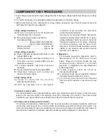
Page 35: ...14 and 10 NOTE Before following the particular steps listed above in the trouble shooting guide for failure please check for the continuity of each wire harness between the tact switch keyboard and PC...

Page 36: ...igher voltage batteries should be used to check the front back resistance of the diode otherwise an infinite resistance may be read in both directions Anormal diodes resistance will be infinite in one...

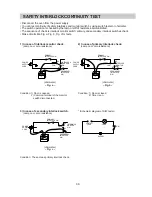
Page 37: ...Condition 1 Door is opened 2 Common terminal of the monitor switch disconnected 3 In case of secondary interlock switch Lamp on or zero resistance ohmmeter Fig c Condition The same as primary interlo...

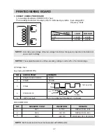
Page 38: ...ble tolerance of the secondary voltage is within 5 of norminal voltage NOTE Each measure point must be measured with GND points 2 Voltage check Key check point MICOM PIN NO CHECK POINT REMARK 1 PIN 21...

Page 39: ...4 7 1 SEGMENT a does not come on from G1 to G5 SEGMENT d 19 8 SEGMENT b does not come on from G1 to G5 SEGMENT e 18 7 SEGMENT c does not come on from G1 to G5 SEGMENT f 16 5 SEGMENT d does not come o...

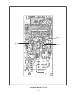
Page 40: ...39 FIG 5 MEASUREMENT POINT MP2 MP3 MP1...

Page 41: ...40 FIG 5 MEASUREMENT POINT...

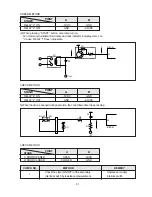
Page 42: ...ate ON OFF of the secondary Replace secondary interlock switch by resistance measurement interlock switch 36 MICOM RY1 D8 24V Q11 A B 40 MICOM A 5V B R8 R11 SW D O M R7 C3 1 2 CHECK METHOD CHECK METHO...

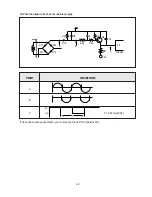
Page 43: ...lock does not operate properly 44 C8 D10 R26 R24 R27 A B 5V C C6 Q8 C4 MICOM D12 D11 D13 D14 8 9 R21 R23 POINT WAVEFORM A B C T 16 67 ms 60Hz 5V 0V T If clock does not keep exact time you must check D...

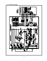
Page 44: ...43 2 P C B CIRCUIT DIAGRAM...

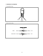
Page 45: ...44 1 Transistor NPN Type 2 Diode and zener diode Emitter Collecftor Base Cathode k Cathode k ANODE A D1 16 ANODE A ZD1 6 DIODE ZENER DIODE 3 COMPONENT INFORMATION...

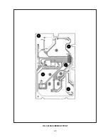
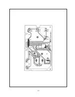
Page 46: ...45 4 PRINTED CIRCUITS BOARD...

Page 47: ...46...

Page 48: ...ER D1 D5 D10 1N4148 DZN4148 6 21 DIODE RECTIFIER D8 D9 D11 D14 1N4002A DZN4002A 6 22 DIODE SWITCHING D6 1N4148M DZN4148M 1 23 DIODE ZENER ZD1 ZD5 MTZ3 9B DZTZ3R9B 2 24 DIODE ZENER ZD2 MTZ5 6B DZTZ5R6B...

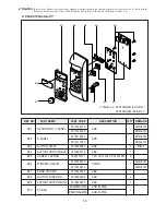
Page 49: ...ON PARTCODE Q TY 1 PCB SUB M157 M157 3514313861 1 2 LED L102 SLR 34VR DSLR34VR 1 3 SWITCH TACT SW101 SW109 KPT 1115AM 5S50101Z93 9 4 SWITCH TACT CN101 HLEM15R 1 4CW215RBD0 1 5 LED L101 DLY 5013T DLY 5...

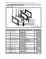
Page 50: ...816T 3511706100 KOR 61150S KOR 616T A06 BARRIER SCREEN I 3517002900 PE 0 1T 1 KOR 816T 3517002800 KOR 616T A07 GASKET DOOR 3512300400 PP 1 KOR 816T 3512300200 KOR 616T A08 HOOK 3513100710 POM 1 A09 SP...

Page 51: ...PAN 3X10 PW MFZN 9 B06 WINDOW DISPLAY 3515500910 PMMA 1 KOR 816T 3515500810 KOR 616T B07 KNOB VOLUME 3513403810 ABS 1 B08 BUTTON FUNCTION 3516905600 ABS 1 B09 BUTTON FUNCTION AUTO 3516905910 ABS 1 B10...

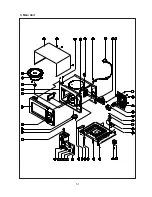
Page 52: ...51 3 Main Unit...

Page 53: ...30 GLASS 1 F20 SCREW TAPTITE 7272400811 TT3 TRS 4X8 MFZN 1 F21 HOLDER HV CAPACITOR 3513001900 SECC T0 8 1 F22 CAPACITOR HV 4415U23010 2100VAC 0 84 F 1 816T 441L267010 2100VAC 0 70 F 1 616T F23 DIODE H...

Page 54: ...P001 DAEWOO ELECTRONICS CO LTD 686 AHYEON DONG MAPO GU SEOUL KOREA C P O BOX 8003 SEOUL KOREA TELEX DWELEC K28177 8 CABLE DAEWOOELEC FAX 02 360 8184 TEL 02 360 8183 http www dwe daewoo co kr PRINTED D...

Reviews: