4
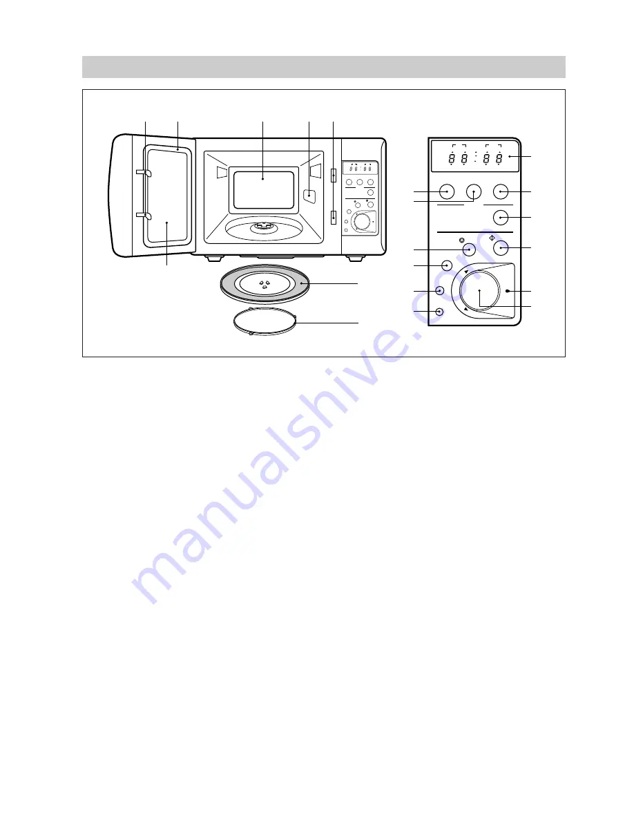
FEATURES DIAGRAM
Power
Defrost
+1min
Auto Cook
STOP
START
CLEAR
Speedy
More
Less
Clock
Tim
er
/W
ei
gh
t/Q
ua
nt
ity
1. Beveroge
2. Soup
3. Casserole
4. Vegetable
5. Fish Fillets
Stop
Defrost
1
2
Weight
Quantity
Time
Lock
Auto cook
Watt
g
Power
Defrost
+1min
Auto Cook
STOP
START
CLEAR
Speedy
More
Less
Clock
Tim
er
/W
ei
gh
t/Q
ua
nt
ity
1. Beveroge
2. Soup
3. Casserole
4. Vegetable
5. Fish Fillets
Stop
Defrost
1
2
Weight
Quantity
Time
Lock
Auto cook
Watt
g
1
2
3
4
5
6
7
8
0
q
t
y
u
i
o
p
r
e
w
9
1
Door latch - When the door is closed it will automatically lock shut. If the door is opened while the
oven is operating, magnetron will immediately stop operating.
2
Door seal - Door seal maintains the microwave energy within the oven cavity and prevents microwave
leakage.
3
Oven cavity.
4
Spatter shield - Protects the microwave outlet from splashes of cooking foods.
5
Safety interlock system.
6
Door viewing screen - Allows viewing of food. The screen is designed so that light can pass through,
but not the microwaves.
7
Glass cooking tray - Made of special heat resistant glass. Food in a proper receptacle is placed on
this tray for cooking.
8
Roller guide - This must always be used for cooking together with the glass cooking tray.
9
Display - Cooking time, power level, present time are displayed.
0 q e
Function buttons - Used to select desired oven operation.
: MICROWAVE, DEFROST, AUTOCOOK.
w
+1 min. button - Used to increase time of operating.
r
Start button - Used to start a selected operation. When lamp blinks, press the start button.
Speedy cook button - Used to set desired time.(It is incresed 30 seconds.)
t
Stop/clear button - Used to pause or clear all information manually put into the oven control panel
except clock.
y u
More/Less button - Used to select auto cook time. (More/less 10% of auto cook time)
i
Clock button - Used to set and recall the time of day.
o
Dial knob - Used to set the cooking time, weight and quantity.
p
Guide lamp - When blinking it informs you to be ready to operte dial knob.
Summary of Contents for KOR-616T0P
Page 40: ...39 FIG 5 MEASUREMENT POINT MP2 MP3 MP1...
Page 41: ...40 FIG 5 MEASUREMENT POINT...
Page 44: ...43 2 P C B CIRCUIT DIAGRAM...
Page 46: ...45 4 PRINTED CIRCUITS BOARD...
Page 47: ...46...
Page 52: ...51 3 Main Unit...


