background image

33

FB12

HFFTB2601B COIL CHIP BEAD

TB321611Z260

FB13

HFFTB2601B COIL CHIP BEAD

TB321611Z260

FB14

HFFTB2601B COIL CHIP BEAD

TB321611Z260

FB15

HFFTB2601B COIL CHIP BEAD

TB321611Z260

FB16

HFFTB2601B COIL CHIP BEAD

TB321611Z260

FB17

HFFTB2601B COIL CHIP BEAD

TB321611Z260

FB18

HFFTB2601B COIL CHIP BEAD

TB321611Z260

FB19

HFFTB2601B COIL CHIP BEAD

TB321611Z260

FB2

HFFTB2601B COIL CHIP BEAD

TB321611Z260

FB20

HFFTB2601B COIL CHIP BEAD

TB321611Z260

FB3

HFFTB2601B COIL CHIP BEAD

TB321611Z260

FB4

HFFTB2601B COIL CHIP BEAD

TB321611Z260

FB7

HFFTB2601B COIL CHIP BEAD

TB321611Z260

FB8

HFFTB2601B COIL CHIP BEAD

TB321611Z260

FB9

HFFTB2601B COIL CHIP BEAD

TB321611Z260

IC801 1KA3842B--

IC POWER

KA3842B

IC802 1KA78R05--

IC REGULATOR

KA78R05

IC803 1KA278R33-

IC REGULATOR

KA278R33

IC804 1TLP721GR-

IC PHOTO COUPLER TLP721D4GR

IC805 1KA431ZTA-

IC SHUNT

KA431ZTA

IC811 1KA78R05--

IC REGULATOR

KA78R05

INV1

DFL11501--

LCD INVERTER

FLI-1501

L801

5PDLF2323-

FILTER LINE

DLF-2323

L811

5MC0000003 COIL CHOKE

L-82

LCD

9979615042

LCD PANEL

L150X2M

LED1 DSD50GYW-- LED

SD50GYW(GREEN/AMBER)

PCB1 9979800571

PCB MAIN

T=1.6*138*100 (L510B1)

PCB2 9979800560

PCB POWER

T=1.6*162*102.5(L510B)

PCB3 9979800566

PCB CONTROL

T=1.6*246*122

Q1

TKTC3875SY TR CHIP

KTC3875SY(RTK)

Q2

TKTC3875SY TR CHIP

KTC3875SY(RTK)

Q3

TKTC3875SY TR CHIP

KTC3875SY(RTK)

Q4

TKTC3875SY TR CHIP

KTC3875SY(RTK)

Q5

TKTC3875SY TR CHIP

KTC3875SY(RTK)

Q6

TNDS9958--

FET CHIP

NDS9958

Q801

TSSS6N70A- FET

SSS6N70A

Q802

TZTC3198Y-

TR

KTC3198Y-(1815Y) (AUTO)

Q810

TZTC3202Y-

TR

KTC3202Y (AUTO)(1959Y)

R1

HRFS105JBA R CHIP

1/16  1M OHM J 1608

R10

HRFS101JBA R CHIP

1/16  100 OHM J 1608

R11

HRFS101JBA R CHIP

1/16  100 OHM J 1608

R12

HRFS153JBA R CHIP

1/16  15K OHM J 1608

R13

HRFS102JBA R CHIP

1/16  1K OHM J 1608

R14

HRFS472JBA R CHIP

1/16  4.7K OHM J 1608

R16

HRFS102JBA R CHIP

1/16  1K OHM J 1608

R17

HRFS102JBA R CHIP

1/16  1K OHM J 1608

R18

HRFS472JBA R CHIP

1/16  4.7K OHM J 1608

R19

HRFS472JBA R CHIP

1/16  4.7K OHM J 1608

LOC

PART-CODE

PART-NAME PART-DESC

R2

HRFS472JBA R CHIP

1/16  4.7K OHM J 1608

R20

HRFS472JBA R CHIP

1/16  4.7K OHM J 1608

R21

HRFS472JBA R CHIP

1/16  4.7K OHM J 1608

R22

HRFS472JBA R CHIP

1/16  4.7K OHM J 1608

R23

HRFS472JBA R CHIP

1/16  4.7K OHM J 1608

R24

HRFS472JBA R CHIP

1/16  4.7K OHM J 1608

R25

HRFS472JBA R CHIP

1/16  4.7K OHM J 1608

R26

HRFS472JBA R CHIP

1/16  4.7K OHM J 1608

R29

HRFS220JBA R CHIP

1/16W 22 OHM J 1608

R3

HRFS101JBA R CHIP

1/16  100 OHM J 1608

R30

HRFS472JBA R CHIP

1/16  4.7K OHM J 1608

R31

HRFS101JBA R CHIP

1/16  100 OHM J 1608

R32

HRFS101JBA R CHIP

1/16  100 OHM J 1608

R33

HRFS221JBA R CHIP

1/16  220 OHM J 1608

R34

HRFS472JBA R CHIP

1/16  4.7K OHM J 1608

R35

HRFS472JBA R CHIP

1/16  4.7K OHM J 1608

R36

HRFS472JBA R CHIP

1/16  4.7K OHM J 1608

R37

HRFS221JBA R CHIP

1/16  220 OHM J 1608

R38

HRFS472JBA R CHIP

1/16  4.7K OHM J 1608

R39

HRFS472JBA R CHIP

1/16  4.7K OHM J 1608

R4

HRFS223JBA R CHIP

1/16  22K OHM J 1608

R40

HRFS102JBA R CHIP

1/16  1K OHM J 1608

R41

HRFS102JBA R CHIP

1/16  1K OHM J 1608

R42

HRFS472JBA R CHIP

1/16  4.7K OHM J 1608

R43

HRFS101JBA R CHIP

1/16  100 OHM J 1608

R44

HRFS101JBA R CHIP

1/16  100 OHM J 1608

R45

HRFS000JBA R CHIP

1/16  0 OHM J 1608

R46

HRFS472JBA R CHIP

1/16  4.7K OHM J 1608

R47

HRFS750JBA R CHIP

1/16W 75 OHM J 1608

R48

HRFS750JBA R CHIP

1/16W 75 OHM J 1608

R49

HRFS750JBA R CHIP

1/16W 75 OHM J 1608

R50

HRFS101JBA R CHIP

1/16  100 OHM J 1608

R51

HRFS101JBA R CHIP

1/16  100 OHM J 1608

R52

HRFS472JBA R CHIP

1/16  4.7K OHM J 1608

R53

HRFS472JBA R CHIP

1/16  4.7K OHM J 1608

R54

HRFS512JBA R CHIP

1/16  5.1K OHM J 1608

R56

HRFS472JBA R CHIP

1/16  4.7K OHM J 1608

R57

HRFS472JBA R CHIP

1/16  4.7K OHM J 1608

R58

HRFS472JBA R CHIP

1/16  4.7K OHM J 1608

R59

HRFS472JBA R CHIP

1/16  4.7K OHM J 1608

R60

HRFS472JBA R CHIP

1/16  4.7K OHM J 1608

R61

HRFS472JBA R CHIP

1/16  4.7K OHM J 1608

R63

HRFS105JBA R CHIP

1/16  1M OHM J 1608

R64

HRFS102JBA R CHIP

1/16  1K OHM J 1608

R65

HRFS102JBA R CHIP

1/16  1K OHM J 1608

R66

HRFS102JBA R CHIP

1/16  1K OHM J 1608

R67

HRFS220JBA R CHIP

1/16W 22 OHM J 1608

R68

HRFS472JBA R CHIP

1/16  4.7K OHM J 1608

LOC

PART-CODE

PART-NAME PART-DESC

!

Summary of Contents for L510B1

Page 1: ...DAEWOO ELECTRONICS CO LTD http svc dwe co kr Service Manual XGA COLOR MONITOR Model L510B1 September 2001...

Page 2: ...RAL INFORMATION 7 PIN CONNECTOR 8 CAUTIONS FOR ADJUSTMENT AND REPAIR 8 OPERATION ADJUSTMENT 9 ALIGNMENT PROCEDURE 14 TROUBLESHOOTING HINTS 15 BLOCK DIAGRAM 22 PCB LAYOUT 23 SCHEMATIC DIAGRAM 27 EXPLOD...

Page 3: ...oltage circuit area if a short circuit is found replace all parts which have been overheated as a result of the short circuit All the protective devices must be reinstalled per original design Solderi...

Page 4: ...nts indicate a personal injury hazard not immediately accessible as one reads the marking or a hazard which is properly included on the equipment itself WARNING Statements are clearly concerning indic...

Page 5: ...herwise specified in this service manual only clean electrical contacts by applying the following mixture to the contacts with a pipe cleaner cotton tipped stick or comparable nonabrasive applicator 1...

Page 6: ...ctrically shorted together by conductive foam aluminum foil or comparable conductive material 7 Immediately before removing the protective material from the leads of replacement ES devices touch the p...

Page 7: ...uit board 2 Carefully bend each IC lead against the circuit foil pad and solder it 3 Clean the soldered areas with a small wire bristle brush lt is not necessary to reapply acrylic coating to the area...

Page 8: ...ngle 75 Right Left 70 up 70 down Contrast Ratio 350 1 contrast ratio typ Brightness 250cd m2 brightness typ Color Filter RGB vertical stripe Synchronization Horizontal 30 62KHz Vertical 50 75Hz Video...

Page 9: ...and a maximum vertical resolution of 768 lines for superior clarity of display By accepting analog signal inputs which level is zero to 0 7 Volts This TFT LCD monitor can display and 262 144 colors d...

Page 10: ...has been done by a color analyzer in factroy The adjustment procedure described in the service manual is made by a visual check Allow 20 minutes warm up time for the display before checking or adjusti...

Page 11: ...U button turns the OSD window on This button moves from top menu to sub menu in the OSD window The button moves cursor to the left or high window in the OSD window This button decreases the value of a...

Page 12: ...10 Key Process OSD OFF MENU EXIT EXIT MENU EXIT MENU OSD OSD SHARPNESS SHARPNESS MENU UT L TY UT L TY UT L TY...

Page 13: ...AUTO POSITION Is the H Size proper Is the noise displayed on the screen Perform the AUTO TRACKING Is the noise displayed on the screen yet Is the noise displayed on the screen yet Adjust the CLOCK FIN...

Page 14: ...left or right and vertically up or down H CENTER V CENTER Choose different preset color temperatures or set your own customized color parameters Adjust the width horizontal size of the screen image Sh...

Page 15: ...ks if the status of the monitor is No Signal or Out of range No Signal screen is displayed when the D Sub signal connector is not connected or the status of the monitor is on DPMS mode Out of Range sc...

Page 16: ...ce mode Adjustment 1 Smart scaling set to 69 2 Contrast set to 90 3 Brightness set to 50 4 Switching to factory alignment mode Press power key with Brightness left key at the power off status 5 Video...

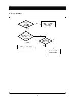
Page 17: ...tect Is a input H sync of ADC pin 90 U2 correct Abnormal mode detect No No Yes Yes Is waveform of pin 81 of ADC U2 correct Trouble in the H sync input circuit Trouble in ADC Trouble in Scaler U1 Yes T...

Page 18: ...ent circuit Check the power board 5VS of CN2A Check on Scaler U1 Is the Power LED toggled between on and off Off No Yes On Is the power cord well connected Refer to No video or No raster Check if the...

Page 19: ...in pin 1 of CN4A power board No No Yes Yes Is the output of inverter correct Check the output of D811 power board Replace the inverter Replace a LCD panal 2 5 2 5 Check the output of Q2 or pin 3 of U3...

Page 20: ...signal of Scaler No Yes Is the input signal normal Check the video signal cable or R G B con ass y Trouble in the soldering of R G B data lines from output of ADC to Scaler U1 Yes No Yes Are the R G...

Page 21: ...No Yes Next page No Yes Connection trouble Check the output of scalier pin 71 72 73 74 75 and soldering of CN5 No Yes Is pin 1 of Q6 3 3V Check Q6 its ambient circuit and pin 27 of com Check if the CN...

Page 22: ...Yes No Yes Is the output of ADC correct No Yes Is the input of ADC correct Check the video input signal Replace the main board or replace ADC Yes Check If the CN5 wafer is well connected at the LCD pa...

Page 23: ...Check 5VS 5VD 5VA 6V 3 3V of CN2A Check the main board Is the power cord well connected Check if the power cord is correctly connected Is the output of D812 6 2V Yes Check ambient circuit of IC801 No...

Page 24: ...ght Panel dirver Output Video Rate H 48 62kHz V 60 75Hz Resolution only 1024 768 Dot clock 65 80MHz 8 Address data line 8bit Clamp I2C bus Inverter On Off 12V Panel 650Vac 50KHz Dimming control 3 3V 5...

Page 25: ...23 24 Main PCB Component Side Main PCB Solder Side PCB LAYOUT...

Page 26: ...25 Control PCB Component Side Control PCB Solder Side...

Page 27: ...26 Power D Sub PCB Component Side Power D Sub PCB Solder Side...

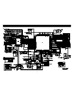
Page 28: ...27 Main Section SCHEMATIC DIAGRAM...

Page 29: ...SMPS Section 28...

Page 30: ...29 EXPLODED VIEW MECHANICAL PARTS LIST...

Page 31: ...0 5 F 1pF J 5 K 10 P 100 0 Z 80 Fig Part No Description Index R101 Resistors RD 4Z820J Carbon 82J R30 HRFS472JBA Chip 4 7K OHM J Tolerance F 1 J 5 K 10 M 20 G 2 Important Safety Notice Components iden...

Page 32: ...ents identified by mark have special characteristics important for safety and x ray radiation These should be replaced only with the types specified in the parts list LOC PART CODE PART NAME PART DESC...

Page 33: ...1MF K 1608 C90 HCFK104ZBA C CHIP CERA 50V Y5V 0 1MF Z 1608 C91 HCFK104ZBA C CHIP CERA 50V Y5V 0 1MF Z 1608 C92 HCFK104ZBA C CHIP CERA 50V Y5V 0 1MF Z 1608 C93 HCEKF100MC C CHIP ELECTRO MV 16V 10MF D4...

Page 34: ...HM J 1608 LOC PART CODE PART NAME PART DESC R2 HRFS472JBA R CHIP 1 16 4 7K OHM J 1608 R20 HRFS472JBA R CHIP 1 16 4 7K OHM J 1608 R21 HRFS472JBA R CHIP 1 16 4 7K OHM J 1608 R22 HRFS472JBA R CHIP 1 16 4...

Page 35: ...4 5 1K OHM J RP1 HFFH4M301E COIL CHIP BEAD HB 4M3216 301JT RP10 HFFH4M301E COIL CHIP BEAD HB 4M3216 301JT LOC PART CODE PART NAME PART DESC RP14 HRTS8E220J R CHIP ARRAY 1 16 8P 22 OHM J 3216 RP15 HRTS...

Page 36: ...DAEWOO ELECTRONICS CO LTDD 686 AHYEON DONG MAPO GU SEOUL KOREA C P O BOX 8003 SEOUL KOREA TELEX DWELEC K28177 8 CABLE DAEWOOELEC...

Reviews: