
S0103010K
Page 28
Wheel Loader Safety
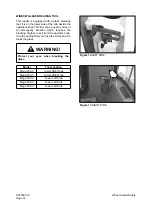
WELDING REPAIRS
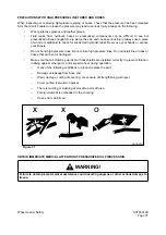
When carrying out welding repairs, carry out the welding in a properly equipped place. The welding should
be performed by a qualified worker. During welding operations, there is the danger of, generation of gas,
fire, or electric shock, so never let an unqualified worker do welding.
The qualified welder must do the following;
•
To prevent explosion of the battery, disconnect the battery terminals and remove batteries.
•
To prevent generation of gas, remove the paint from the location of the weld.
•
If hydraulic equipment, piping or places close to them are heated, a flammable gas or mist will
be generated and there is danger of it catching fire. To avoid this, never subject these places to
heat.
•
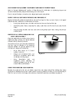
Do not weld on pipes or on tubes that contain flammable fluids. Do not flame cut on pipes or on
tubes that contain flammable fluids. Before you weld on pipes or on tubes or before you flame
cut on pipes or on tubes, clean the pipes or tubes thoroughly with a nonflammable solvent.
•
If heat is applied directly to rubber hoses or piping under pressure, they may suddenly break so
cover them with a fireproof covering.
•
Wear protective clothing.
•
Make sure there is good ventilation.
•
Remove all flammable objects and provide a fire extinguisher.
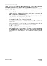
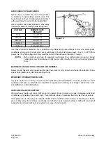
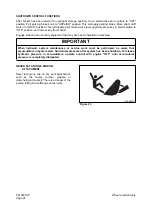
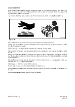
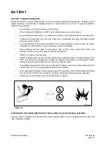
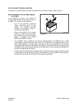
PRECAUTIONS FOR REMOVAL,
INSTALLATION, AND STORAGE OF
ATTACHMENTS
Before starting removal and installation of
attachments, decide the team leader.
Do not allow anyone except the authorized
workers close to the machine or attachment.
Place attachments that have been removed
from the machine in a safe place so that they do
not fall. Put up a fence around the attachments
and take other measures to prevent
unauthorized persons from entering.
HDO1041L
Figure 29
Summary of Contents for Mega 500-V
Page 4: ...1SAFETY ...
Page 41: ...1SPECIFICATIONS ...
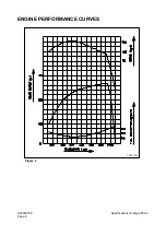
Page 47: ...S0203070K Page 6 Specifications for Mega 500 V ENGINE PERFORMANCE CURVES AHS3720L Figure 2 ...
Page 55: ...S0203070K Page 14 Specifications for Mega 500 V ...
Page 56: ...1GENERAL MAINTENANCE ...
Page 70: ...S0302000 Page 14 General Maintenance Procedures Return to Master Table of Contents ...
Page 83: ...1UPPER STRUCTURE ...
Page 85: ...S0403040K Page 2 Counterweight TABLE OF CONTENTS Specifications 3 Counterweight 3 ...
Page 87: ...S0403040K Page 4 Counterweight ...
Page 98: ...1LOWER STRUCTURE AND CHASSIS ...
Page 104: ...S0502020K Page 6 Center Joint Articulation Joint ...
Page 105: ...1ENGINE AND DRIVE TRAIN ...
Page 118: ...S0602170K Page 13 Axle ZF AP 420R Figure 9 ...
Page 119: ...S0602170K Page 14 Axle ZF AP 420R ...
Page 121: ...S0602170K Page 16 Axle ZF AP 420R FINAL DRIVE AP 407 409 Figure 10 ...
Page 123: ...S0602170K Page 18 Axle ZF AP 420R AP 411 415 Figure 11 ...
Page 125: ...S0602170K Page 20 Axle ZF AP 420R AP 417 420 Figure 12 ...
Page 129: ...S0602170K Page 24 Axle ZF AP 420R Differential Carrier RK Figure 14 ...
Page 131: ...S0602170K Page 26 Axle ZF AP 420R Differential Carrier DK ...
Page 135: ...S0602170K Page 30 Axle ZF AP 420R Differential Carrier HK Figure 16 ...
Page 178: ...S0602170K Page 73 Axle ZF AP 420R ILLUSTRATED TABLE Figure 152 ...
Page 194: ...S0602170K Page 89 Axle ZF AP 420R ILLUSTRATED TABLE Figure 196 ...
Page 210: ...S0602170K Page 105 Axle ZF AP 420R ILLUSTRATED TABLE Figure 242 ...
Page 225: ...S0602170K Page 120 Axle ZF AP 420R ILLUSTRATED TABLE Figure 289 ...
Page 251: ...S0605050K Page 26 Air Conditioner Return to Master Table of Contents ...
Page 261: ...S0607080K Page 10 Transmission and Torque Converter ZF 4WG 310 Figure 2 ...
Page 264: ...S0607080K Page 13 Transmission and Torque Converter ZF 4WG 310 ...
Page 271: ...S0607080K Page 20 Transmission and Torque Converter ZF 4WG 310 ...
Page 296: ...S0607080K Page 45 Transmission and Torque Converter ZF 4WG 310 ...
Page 447: ...S0607900C Page 36 Transmission Error Codes ZF ...
Page 448: ...1HYDRAULICS ...
Page 478: ...S0705010 Page 22 Cylinders Return to Master Table of Contents ...
Page 489: ...S0708460K Page 11 Main Pump Denison T6DMY Series ...
Page 490: ...S0708460K Page 12 Main Pump Denison T6DMY Series PARTS LIST Figure 8 ...
Page 504: ...S0708460K Page 26 Main Pump Denison T6DMY Series ...
Page 508: ...S0708470K Page 4 Steering and Brake Pump Denison T67DB Series PARTS LIST Figure 2 ...
Page 514: ...S0708470K Page 10 Steering and Brake Pump Denison T67DB Series DISASSEMBLY Figure 5 ...
Page 521: ...S0708470K Page 17 Steering and Brake Pump Denison T67DB Series ...
Page 522: ...S0708470K Page 18 Steering and Brake Pump Denison T67DB Series REASSEMBLY Figure 15 ...
Page 528: ...S0708470K Page 24 Steering and Brake Pump Denison T67DB Series ...
Page 548: ...S0709476K Page 2 Pilot Control Valve Return to Master Table of Contents ...
Page 554: ...S0709476K Page 8 Pilot Control Valve Return to Master Table of Contents ...
Page 557: ...S0709665K Page 3 Flow Amplifier Danfoss GENERAL DESCRIPTION Figure 1 ...
Page 558: ...S0709665K Page 4 Flow Amplifier Danfoss PARTS LIST Figure 2 ...
Page 609: ...S0709730K Page 7 Power Steering Unit Return to Master Table of Contents ...
Page 632: ...S0709730K Page 30 Power Steering Unit Return to Master Table of Contents ...
Page 638: ...S0709750K Page 6 Restriction Valve Return to Master Table of Contents ...
Page 644: ...S0793060K Page 6 Hydraulic Schematic Mega 500 V Return to Master Table of Contents ...
Page 645: ...1ELECTRICAL SYSTEM ...
Page 654: ...S0802190K Page 9 Electrical System Return to Master Table of Contents ...
Page 658: ...S0802190K Page 13 Electrical System Return to Master Table of Contents ...
Page 676: ...S0802190K Page 31 Electrical System Return to Master Table of Contents ...
Page 685: ...S0893060K Page 6 Electrical Schematic Mega 500 V Return to Master Table of Contents ...
Page 686: ...1ATTACHMENTS ...


