
S0607080K
Page 159
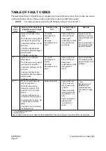
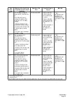
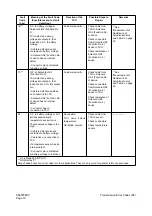
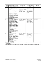
Transmission and Torque Converter
(ZF 4WG-310)
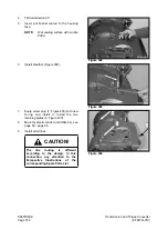
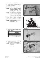
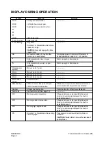
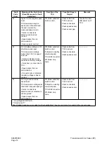
C.
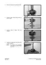
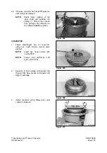
Measure Dimension II from the
contact face to the mounting face.
NOTE:
Dimension II e.g. 39.00 mm
(1.5354 in).
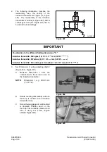
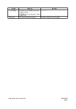
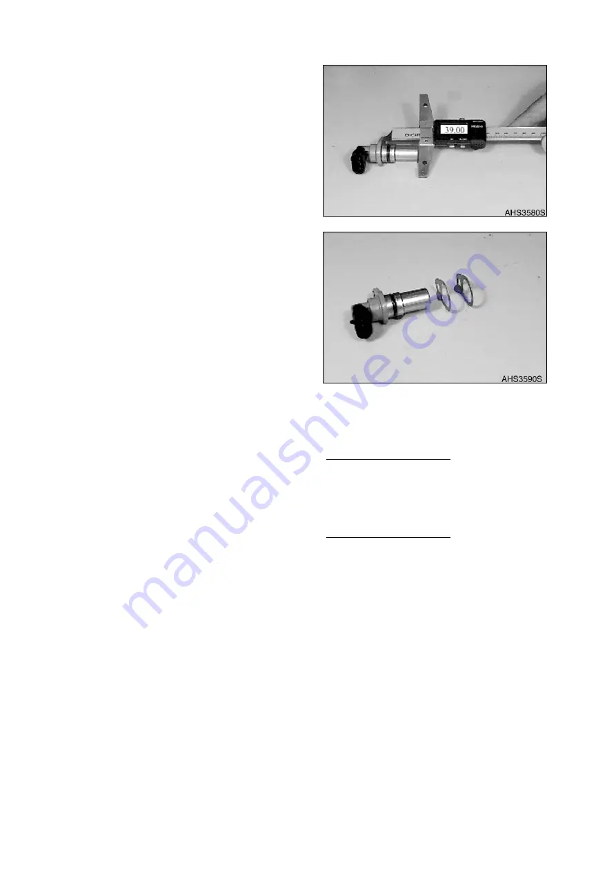
D.
Line up setting plates (2x, s = 0.5 mm
(0.0197 in)) and grease O-ring.
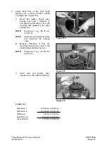
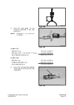
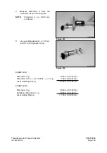
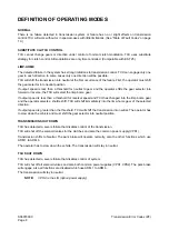
EXAMPLE N1:
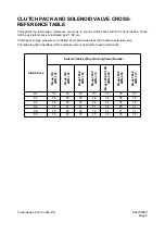
EXAMPLE N2:
Dimension I e.g.
39.20 mm (1.5433 in)
Dimension X (1.0
+ 0.3
mm (0.0394
+ 0.0118
in) e.g.
- 1.20 mm (0.0472 in)
Gives Adjusting Disk (s)
= 38.00 mm (1.4961 in)
Dimension I e.g.
39.00 mm (1.5354 in)
Installation Dimension A e.g.
- 38.00 mm (1.4961 in)
Gives Setting Plate (s)
= 1.00 mm (0.0394 in)
Figure 413
Figure 414
Summary of Contents for Mega 500-V
Page 4: ...1SAFETY ...
Page 41: ...1SPECIFICATIONS ...
Page 47: ...S0203070K Page 6 Specifications for Mega 500 V ENGINE PERFORMANCE CURVES AHS3720L Figure 2 ...
Page 55: ...S0203070K Page 14 Specifications for Mega 500 V ...
Page 56: ...1GENERAL MAINTENANCE ...
Page 70: ...S0302000 Page 14 General Maintenance Procedures Return to Master Table of Contents ...
Page 83: ...1UPPER STRUCTURE ...
Page 85: ...S0403040K Page 2 Counterweight TABLE OF CONTENTS Specifications 3 Counterweight 3 ...
Page 87: ...S0403040K Page 4 Counterweight ...
Page 98: ...1LOWER STRUCTURE AND CHASSIS ...
Page 104: ...S0502020K Page 6 Center Joint Articulation Joint ...
Page 105: ...1ENGINE AND DRIVE TRAIN ...
Page 118: ...S0602170K Page 13 Axle ZF AP 420R Figure 9 ...
Page 119: ...S0602170K Page 14 Axle ZF AP 420R ...
Page 121: ...S0602170K Page 16 Axle ZF AP 420R FINAL DRIVE AP 407 409 Figure 10 ...
Page 123: ...S0602170K Page 18 Axle ZF AP 420R AP 411 415 Figure 11 ...
Page 125: ...S0602170K Page 20 Axle ZF AP 420R AP 417 420 Figure 12 ...
Page 129: ...S0602170K Page 24 Axle ZF AP 420R Differential Carrier RK Figure 14 ...
Page 131: ...S0602170K Page 26 Axle ZF AP 420R Differential Carrier DK ...
Page 135: ...S0602170K Page 30 Axle ZF AP 420R Differential Carrier HK Figure 16 ...
Page 178: ...S0602170K Page 73 Axle ZF AP 420R ILLUSTRATED TABLE Figure 152 ...
Page 194: ...S0602170K Page 89 Axle ZF AP 420R ILLUSTRATED TABLE Figure 196 ...
Page 210: ...S0602170K Page 105 Axle ZF AP 420R ILLUSTRATED TABLE Figure 242 ...
Page 225: ...S0602170K Page 120 Axle ZF AP 420R ILLUSTRATED TABLE Figure 289 ...
Page 251: ...S0605050K Page 26 Air Conditioner Return to Master Table of Contents ...
Page 261: ...S0607080K Page 10 Transmission and Torque Converter ZF 4WG 310 Figure 2 ...
Page 264: ...S0607080K Page 13 Transmission and Torque Converter ZF 4WG 310 ...
Page 271: ...S0607080K Page 20 Transmission and Torque Converter ZF 4WG 310 ...
Page 296: ...S0607080K Page 45 Transmission and Torque Converter ZF 4WG 310 ...
Page 447: ...S0607900C Page 36 Transmission Error Codes ZF ...
Page 448: ...1HYDRAULICS ...
Page 478: ...S0705010 Page 22 Cylinders Return to Master Table of Contents ...
Page 489: ...S0708460K Page 11 Main Pump Denison T6DMY Series ...
Page 490: ...S0708460K Page 12 Main Pump Denison T6DMY Series PARTS LIST Figure 8 ...
Page 504: ...S0708460K Page 26 Main Pump Denison T6DMY Series ...
Page 508: ...S0708470K Page 4 Steering and Brake Pump Denison T67DB Series PARTS LIST Figure 2 ...
Page 514: ...S0708470K Page 10 Steering and Brake Pump Denison T67DB Series DISASSEMBLY Figure 5 ...
Page 521: ...S0708470K Page 17 Steering and Brake Pump Denison T67DB Series ...
Page 522: ...S0708470K Page 18 Steering and Brake Pump Denison T67DB Series REASSEMBLY Figure 15 ...
Page 528: ...S0708470K Page 24 Steering and Brake Pump Denison T67DB Series ...
Page 548: ...S0709476K Page 2 Pilot Control Valve Return to Master Table of Contents ...
Page 554: ...S0709476K Page 8 Pilot Control Valve Return to Master Table of Contents ...
Page 557: ...S0709665K Page 3 Flow Amplifier Danfoss GENERAL DESCRIPTION Figure 1 ...
Page 558: ...S0709665K Page 4 Flow Amplifier Danfoss PARTS LIST Figure 2 ...
Page 609: ...S0709730K Page 7 Power Steering Unit Return to Master Table of Contents ...
Page 632: ...S0709730K Page 30 Power Steering Unit Return to Master Table of Contents ...
Page 638: ...S0709750K Page 6 Restriction Valve Return to Master Table of Contents ...
Page 644: ...S0793060K Page 6 Hydraulic Schematic Mega 500 V Return to Master Table of Contents ...
Page 645: ...1ELECTRICAL SYSTEM ...
Page 654: ...S0802190K Page 9 Electrical System Return to Master Table of Contents ...
Page 658: ...S0802190K Page 13 Electrical System Return to Master Table of Contents ...
Page 676: ...S0802190K Page 31 Electrical System Return to Master Table of Contents ...
Page 685: ...S0893060K Page 6 Electrical Schematic Mega 500 V Return to Master Table of Contents ...
Page 686: ...1ATTACHMENTS ...


