


S0708470K
Page 7
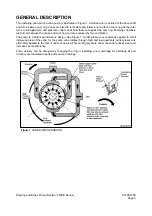
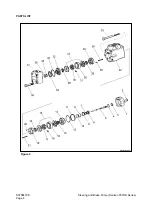
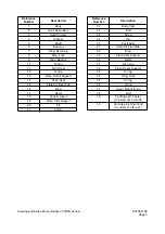
Steering and Brake Pump (Denison T67DB Series)
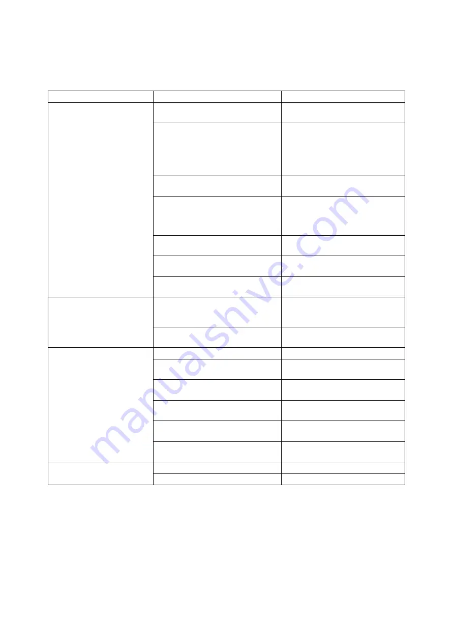
TROUBLESHOOTING, TESTING AND ADJUSTMENT
Table below lists the common difficulties experienced with vane pumps and hydraulic systems. It indicates,
possible causes and remedies for each of the problems listed.
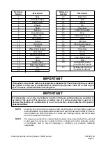
Problem
Possible Cause
Remedy
Excessive noise in pump.
Low oil level in reservoir.
Fill reservoir to proper level with
recommended fluid.
Air in system.
Open reservoir cap and operate
system until purged.
Bleed hydraulic lines at highest
point down stream of pump while
system is under pressure.
Vacuum
condition.
Check inlet (suction) line and
fittings for air leaks.
Oil too thick.
Be certain correct type of oil is
used in system. Warm up pump in
cold weather until noise
disappears.
Damaged or missing pump seals at
mating surfaces.
Locate and replace damaged or
missing seals.
Cartridge kit not assembled
properly.
Reassemble cartridge kit.
Pump inlet/outlet lines reversed.
Reconnect lines to proper port
connections.
Pump
overheating.
Internal
leakage.
If excessive internal leakage
exists, return to shop for complete
overhaul.
Heat
exchanger
not
functioning.
Locate trouble and repair or
replace.
System not developing
pressure.
Relief valve open.
Repair or replace.
Loss of fluid internally (slippage).
Return to shop for evaluation and
repair.
Cartridge kit not assembled
properly.
Reassemble kit.
Cartridge kit assembled for
opposite rotation.
Reassemble kit to proper rotation.
Pump inlet/outlet lines reversed.
Reconnect lines to proper port
connections.
Disconnected or broken drive
mechanism.
Locate and repair.
Loss of fluid.
Ruptured hydraulic lines.
Locate and repair.
Leaking or missing seals.
Locate and repair.
Summary of Contents for Mega 500-V
Page 4: ...1SAFETY ...
Page 41: ...1SPECIFICATIONS ...
Page 47: ...S0203070K Page 6 Specifications for Mega 500 V ENGINE PERFORMANCE CURVES AHS3720L Figure 2 ...
Page 55: ...S0203070K Page 14 Specifications for Mega 500 V ...
Page 56: ...1GENERAL MAINTENANCE ...
Page 70: ...S0302000 Page 14 General Maintenance Procedures Return to Master Table of Contents ...
Page 83: ...1UPPER STRUCTURE ...
Page 85: ...S0403040K Page 2 Counterweight TABLE OF CONTENTS Specifications 3 Counterweight 3 ...
Page 87: ...S0403040K Page 4 Counterweight ...
Page 98: ...1LOWER STRUCTURE AND CHASSIS ...
Page 104: ...S0502020K Page 6 Center Joint Articulation Joint ...
Page 105: ...1ENGINE AND DRIVE TRAIN ...
Page 118: ...S0602170K Page 13 Axle ZF AP 420R Figure 9 ...
Page 119: ...S0602170K Page 14 Axle ZF AP 420R ...
Page 121: ...S0602170K Page 16 Axle ZF AP 420R FINAL DRIVE AP 407 409 Figure 10 ...
Page 123: ...S0602170K Page 18 Axle ZF AP 420R AP 411 415 Figure 11 ...
Page 125: ...S0602170K Page 20 Axle ZF AP 420R AP 417 420 Figure 12 ...
Page 129: ...S0602170K Page 24 Axle ZF AP 420R Differential Carrier RK Figure 14 ...
Page 131: ...S0602170K Page 26 Axle ZF AP 420R Differential Carrier DK ...
Page 135: ...S0602170K Page 30 Axle ZF AP 420R Differential Carrier HK Figure 16 ...
Page 178: ...S0602170K Page 73 Axle ZF AP 420R ILLUSTRATED TABLE Figure 152 ...
Page 194: ...S0602170K Page 89 Axle ZF AP 420R ILLUSTRATED TABLE Figure 196 ...
Page 210: ...S0602170K Page 105 Axle ZF AP 420R ILLUSTRATED TABLE Figure 242 ...
Page 225: ...S0602170K Page 120 Axle ZF AP 420R ILLUSTRATED TABLE Figure 289 ...
Page 251: ...S0605050K Page 26 Air Conditioner Return to Master Table of Contents ...
Page 261: ...S0607080K Page 10 Transmission and Torque Converter ZF 4WG 310 Figure 2 ...
Page 264: ...S0607080K Page 13 Transmission and Torque Converter ZF 4WG 310 ...
Page 271: ...S0607080K Page 20 Transmission and Torque Converter ZF 4WG 310 ...
Page 296: ...S0607080K Page 45 Transmission and Torque Converter ZF 4WG 310 ...
Page 447: ...S0607900C Page 36 Transmission Error Codes ZF ...
Page 448: ...1HYDRAULICS ...
Page 478: ...S0705010 Page 22 Cylinders Return to Master Table of Contents ...
Page 489: ...S0708460K Page 11 Main Pump Denison T6DMY Series ...
Page 490: ...S0708460K Page 12 Main Pump Denison T6DMY Series PARTS LIST Figure 8 ...
Page 504: ...S0708460K Page 26 Main Pump Denison T6DMY Series ...
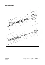
Page 508: ...S0708470K Page 4 Steering and Brake Pump Denison T67DB Series PARTS LIST Figure 2 ...
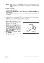
Page 514: ...S0708470K Page 10 Steering and Brake Pump Denison T67DB Series DISASSEMBLY Figure 5 ...
Page 521: ...S0708470K Page 17 Steering and Brake Pump Denison T67DB Series ...
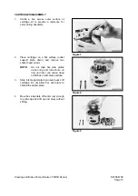
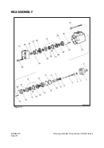
Page 522: ...S0708470K Page 18 Steering and Brake Pump Denison T67DB Series REASSEMBLY Figure 15 ...
Page 528: ...S0708470K Page 24 Steering and Brake Pump Denison T67DB Series ...
Page 548: ...S0709476K Page 2 Pilot Control Valve Return to Master Table of Contents ...
Page 554: ...S0709476K Page 8 Pilot Control Valve Return to Master Table of Contents ...
Page 557: ...S0709665K Page 3 Flow Amplifier Danfoss GENERAL DESCRIPTION Figure 1 ...
Page 558: ...S0709665K Page 4 Flow Amplifier Danfoss PARTS LIST Figure 2 ...
Page 609: ...S0709730K Page 7 Power Steering Unit Return to Master Table of Contents ...
Page 632: ...S0709730K Page 30 Power Steering Unit Return to Master Table of Contents ...
Page 638: ...S0709750K Page 6 Restriction Valve Return to Master Table of Contents ...
Page 644: ...S0793060K Page 6 Hydraulic Schematic Mega 500 V Return to Master Table of Contents ...
Page 645: ...1ELECTRICAL SYSTEM ...
Page 654: ...S0802190K Page 9 Electrical System Return to Master Table of Contents ...
Page 658: ...S0802190K Page 13 Electrical System Return to Master Table of Contents ...
Page 676: ...S0802190K Page 31 Electrical System Return to Master Table of Contents ...
Page 685: ...S0893060K Page 6 Electrical Schematic Mega 500 V Return to Master Table of Contents ...
Page 686: ...1ATTACHMENTS ...


