


S0302000
Page 4
General Maintenance Procedures
Return to Master Table of Contents
HYDRAULIC SYSTEM - GENERAL PRECAUTIONS
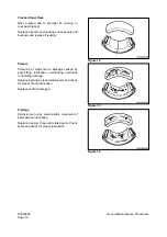
Always maintain oil level in the system at recommended levels. Assemblies that operate under heavy
loads, at high speed, with extremely precise dimensional tolerances between moving parts - pistons and
cylinders, or shoes and swash plates, for example - can be severely damaged if oil supply runs dry.
Assemblies can be run dry and damaged severely in a very short time when piping or hoses are
disconnected to repair leaks and/or replace damaged components. Hoses that are inadvertently switched
during disassembly (inlet for outlet and vice versa), air introduced into the system or assemblies that are
low on oil due to neglect or careless maintenance, could all produce sufficient fluid loss to cause damage.
When starting the engine (particularly after long layoff or storage intervals), make sure that all hydraulic
controls and operating circuits are in neutral, or "OFF." That will prevent pumps or other components that
may be temporarily oil-starved from being run under a load.
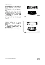
Replacement of any hydraulic system component could require thorough cleaning, flushing, and some
amount of pre-filling with fresh, clean oil if the protective seal on replacement parts has obviously been
broken or if seal integrity may have been compromised. When protective seals are removed before
installation and reassembly, inspect all replacement parts carefully, before they are installed. If the
replacement part is bone dry (with no trace of factory pre-lube) or has been contaminated by dirt or by
questionable oils, flushing and pre-filling with clean hydraulic fluid is recommended.
Vibration, irregular or difficult movement or unusual noise from any part of the hydraulic system could be
an indication of air in the system (and many other types of problems). As a general precaution (and to help
minimize the risk of potential long-term damage), allow the engine to run at no-load idle speed immediately
after initial start-up. Hydraulic fluid will circulate, releasing any air that may have been trapped in the
system before load demands are imposed.
A daily walk-around pre-start equipment safety inspection, including a quick visual scan for any exterior
evidence of leaking hydraulic fluid, can help extend the service life of system components.
CAUTION!
Observe the following safety precautions:
1.
Use extra caution and adequate safety shielding when welding near fuel and oil tanks,
batteries, hydraulic piping lines or other fire hazards.
2.
Never weld when the engine is running. Battery cables must be disconnected before the
welding procedure is started.
3.
Never weld on a wet or damp surface. The presence of moisture causes hydrogen
embrittlement and structural weakening of the weld.
4.
If welding procedures are being performed near cylinder rods, operator’s cab window areas
or any other assemblies that could be damaged by weld spatters, use adequate shielding
protection in front of the assembly.
5.
During equipment setup, always attach ground cables directly to the area or component
being welded to prevent arcing through bearings, bushings, or spacers.
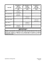
6.
Always use correct welding rods for the type of weld being performed and observe
recommended precautions and time constraints. AWS Class E7018 welding rods for low
alloy to medium carbon steel must be used within two hours after removal from a freshly
opened container. Class E11018G welding rods for T-1 and other higher strength steel must
be used within 1/2 hour.
Summary of Contents for Mega 500-V
Page 4: ...1SAFETY ...
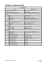
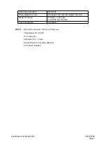
Page 41: ...1SPECIFICATIONS ...
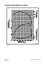
Page 47: ...S0203070K Page 6 Specifications for Mega 500 V ENGINE PERFORMANCE CURVES AHS3720L Figure 2 ...
Page 55: ...S0203070K Page 14 Specifications for Mega 500 V ...
Page 56: ...1GENERAL MAINTENANCE ...
Page 70: ...S0302000 Page 14 General Maintenance Procedures Return to Master Table of Contents ...
Page 83: ...1UPPER STRUCTURE ...
Page 85: ...S0403040K Page 2 Counterweight TABLE OF CONTENTS Specifications 3 Counterweight 3 ...
Page 87: ...S0403040K Page 4 Counterweight ...
Page 98: ...1LOWER STRUCTURE AND CHASSIS ...
Page 104: ...S0502020K Page 6 Center Joint Articulation Joint ...
Page 105: ...1ENGINE AND DRIVE TRAIN ...
Page 118: ...S0602170K Page 13 Axle ZF AP 420R Figure 9 ...
Page 119: ...S0602170K Page 14 Axle ZF AP 420R ...
Page 121: ...S0602170K Page 16 Axle ZF AP 420R FINAL DRIVE AP 407 409 Figure 10 ...
Page 123: ...S0602170K Page 18 Axle ZF AP 420R AP 411 415 Figure 11 ...
Page 125: ...S0602170K Page 20 Axle ZF AP 420R AP 417 420 Figure 12 ...
Page 129: ...S0602170K Page 24 Axle ZF AP 420R Differential Carrier RK Figure 14 ...
Page 131: ...S0602170K Page 26 Axle ZF AP 420R Differential Carrier DK ...
Page 135: ...S0602170K Page 30 Axle ZF AP 420R Differential Carrier HK Figure 16 ...
Page 178: ...S0602170K Page 73 Axle ZF AP 420R ILLUSTRATED TABLE Figure 152 ...
Page 194: ...S0602170K Page 89 Axle ZF AP 420R ILLUSTRATED TABLE Figure 196 ...
Page 210: ...S0602170K Page 105 Axle ZF AP 420R ILLUSTRATED TABLE Figure 242 ...
Page 225: ...S0602170K Page 120 Axle ZF AP 420R ILLUSTRATED TABLE Figure 289 ...
Page 251: ...S0605050K Page 26 Air Conditioner Return to Master Table of Contents ...
Page 261: ...S0607080K Page 10 Transmission and Torque Converter ZF 4WG 310 Figure 2 ...
Page 264: ...S0607080K Page 13 Transmission and Torque Converter ZF 4WG 310 ...
Page 271: ...S0607080K Page 20 Transmission and Torque Converter ZF 4WG 310 ...
Page 296: ...S0607080K Page 45 Transmission and Torque Converter ZF 4WG 310 ...
Page 447: ...S0607900C Page 36 Transmission Error Codes ZF ...
Page 448: ...1HYDRAULICS ...
Page 478: ...S0705010 Page 22 Cylinders Return to Master Table of Contents ...
Page 489: ...S0708460K Page 11 Main Pump Denison T6DMY Series ...
Page 490: ...S0708460K Page 12 Main Pump Denison T6DMY Series PARTS LIST Figure 8 ...
Page 504: ...S0708460K Page 26 Main Pump Denison T6DMY Series ...
Page 508: ...S0708470K Page 4 Steering and Brake Pump Denison T67DB Series PARTS LIST Figure 2 ...
Page 514: ...S0708470K Page 10 Steering and Brake Pump Denison T67DB Series DISASSEMBLY Figure 5 ...
Page 521: ...S0708470K Page 17 Steering and Brake Pump Denison T67DB Series ...
Page 522: ...S0708470K Page 18 Steering and Brake Pump Denison T67DB Series REASSEMBLY Figure 15 ...
Page 528: ...S0708470K Page 24 Steering and Brake Pump Denison T67DB Series ...
Page 548: ...S0709476K Page 2 Pilot Control Valve Return to Master Table of Contents ...
Page 554: ...S0709476K Page 8 Pilot Control Valve Return to Master Table of Contents ...
Page 557: ...S0709665K Page 3 Flow Amplifier Danfoss GENERAL DESCRIPTION Figure 1 ...
Page 558: ...S0709665K Page 4 Flow Amplifier Danfoss PARTS LIST Figure 2 ...
Page 609: ...S0709730K Page 7 Power Steering Unit Return to Master Table of Contents ...
Page 632: ...S0709730K Page 30 Power Steering Unit Return to Master Table of Contents ...
Page 638: ...S0709750K Page 6 Restriction Valve Return to Master Table of Contents ...
Page 644: ...S0793060K Page 6 Hydraulic Schematic Mega 500 V Return to Master Table of Contents ...
Page 645: ...1ELECTRICAL SYSTEM ...
Page 654: ...S0802190K Page 9 Electrical System Return to Master Table of Contents ...
Page 658: ...S0802190K Page 13 Electrical System Return to Master Table of Contents ...
Page 676: ...S0802190K Page 31 Electrical System Return to Master Table of Contents ...
Page 685: ...S0893060K Page 6 Electrical Schematic Mega 500 V Return to Master Table of Contents ...
Page 686: ...1ATTACHMENTS ...


