


S0302000
Page 5
General Maintenance Procedures
Return to Master Table of Contents
MAINTENANCE SERVICE AND REPAIR PROCEDURE
GENERAL PRECAUTIONS
Fluid level and condition should always be checked whenever any other type of maintenance service or
repair is being performed.
NOTE:
If the unit is being used in an extreme temperature environment (in sub-freezing climates
or in high temperature, high humidity tropical conditions), frequent purging of moisture
condensation from the hydraulic reservoir drain tap should be a regular and frequent part
of the operating routine. In more moderate, temperate climates, draining reservoir
sediment and moisture may not be required more than once or twice every few months.
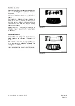
Inspect drained oil and used filters for signs of abnormal coloring or visible fluid contamination at every oil
change. Abrasive grit or dust particles will cause discoloration and darkening of the fluid. Visible
accumulations of dirt or grit could be an indication that filter elements are overloaded (and will require more
frequent replacement) or that disintegrating bearings or other component failures in the hydraulic circuit
may be imminent or have already occurred. Open the drain plugs on the main pump casings and check
and compare drain oil in the pumps. Look for evidence of grit or metallic particles.
Vibration or unusual noise during operation could be an indication of air leaking into the circuit (Refer to the
appropriate Troubleshooting section for component or unit for procedures.), or it may be evidence of a
defective pump. The gear-type pilot pump could be defective, causing low pilot pressure, or a main pump
broken shoe or piston could be responsible.
NOTE:
If equipped, indicated operating pressure, as shown on the multidisplay digital gauge on
the Instrument Panel ("F-Pump" and "R-Pump") will be reduced as a result of a
mechanical problem inside the pump. However, pressure loss could also be due to
cavitation or air leakage, or other faults in the hydraulic system.
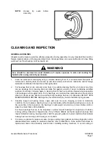
Check the exterior case drain oil in the main pumps. If no metallic particles are found, make sure there is
no air in the system. Unbolt and remove the tank return drain line from the top part of the swing motor, both
travel motors and each main pump. If there is air in any one of the drain lines, carefully pre-fill the
assembly before bolting together the drain line piping connections. Run the system at low rpm.
IMPORTANT
Hydraulic system operating conditions (repetitive cycling, heavy work loads, fluid circulating
under high pressure) make it extremely critical that dust, grit or any other type of contamination
be kept out of the system. Observe fluid and filter change maintenance interval
recommendations and always pre-clean any exterior surface of the system before it is exposed
to air. For example, the reservoir filler cap and neck area, hoses that have to be disassembled,
and the covers and external surfaces of filter canisters should all be cleaned before
disassembly.
Summary of Contents for Mega 500-V
Page 4: ...1SAFETY ...
Page 41: ...1SPECIFICATIONS ...
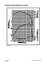
Page 47: ...S0203070K Page 6 Specifications for Mega 500 V ENGINE PERFORMANCE CURVES AHS3720L Figure 2 ...
Page 55: ...S0203070K Page 14 Specifications for Mega 500 V ...
Page 56: ...1GENERAL MAINTENANCE ...
Page 70: ...S0302000 Page 14 General Maintenance Procedures Return to Master Table of Contents ...
Page 83: ...1UPPER STRUCTURE ...
Page 85: ...S0403040K Page 2 Counterweight TABLE OF CONTENTS Specifications 3 Counterweight 3 ...
Page 87: ...S0403040K Page 4 Counterweight ...
Page 98: ...1LOWER STRUCTURE AND CHASSIS ...
Page 104: ...S0502020K Page 6 Center Joint Articulation Joint ...
Page 105: ...1ENGINE AND DRIVE TRAIN ...
Page 118: ...S0602170K Page 13 Axle ZF AP 420R Figure 9 ...
Page 119: ...S0602170K Page 14 Axle ZF AP 420R ...
Page 121: ...S0602170K Page 16 Axle ZF AP 420R FINAL DRIVE AP 407 409 Figure 10 ...
Page 123: ...S0602170K Page 18 Axle ZF AP 420R AP 411 415 Figure 11 ...
Page 125: ...S0602170K Page 20 Axle ZF AP 420R AP 417 420 Figure 12 ...
Page 129: ...S0602170K Page 24 Axle ZF AP 420R Differential Carrier RK Figure 14 ...
Page 131: ...S0602170K Page 26 Axle ZF AP 420R Differential Carrier DK ...
Page 135: ...S0602170K Page 30 Axle ZF AP 420R Differential Carrier HK Figure 16 ...
Page 178: ...S0602170K Page 73 Axle ZF AP 420R ILLUSTRATED TABLE Figure 152 ...
Page 194: ...S0602170K Page 89 Axle ZF AP 420R ILLUSTRATED TABLE Figure 196 ...
Page 210: ...S0602170K Page 105 Axle ZF AP 420R ILLUSTRATED TABLE Figure 242 ...
Page 225: ...S0602170K Page 120 Axle ZF AP 420R ILLUSTRATED TABLE Figure 289 ...
Page 251: ...S0605050K Page 26 Air Conditioner Return to Master Table of Contents ...
Page 261: ...S0607080K Page 10 Transmission and Torque Converter ZF 4WG 310 Figure 2 ...
Page 264: ...S0607080K Page 13 Transmission and Torque Converter ZF 4WG 310 ...
Page 271: ...S0607080K Page 20 Transmission and Torque Converter ZF 4WG 310 ...
Page 296: ...S0607080K Page 45 Transmission and Torque Converter ZF 4WG 310 ...
Page 447: ...S0607900C Page 36 Transmission Error Codes ZF ...
Page 448: ...1HYDRAULICS ...
Page 478: ...S0705010 Page 22 Cylinders Return to Master Table of Contents ...
Page 489: ...S0708460K Page 11 Main Pump Denison T6DMY Series ...
Page 490: ...S0708460K Page 12 Main Pump Denison T6DMY Series PARTS LIST Figure 8 ...
Page 504: ...S0708460K Page 26 Main Pump Denison T6DMY Series ...
Page 508: ...S0708470K Page 4 Steering and Brake Pump Denison T67DB Series PARTS LIST Figure 2 ...
Page 514: ...S0708470K Page 10 Steering and Brake Pump Denison T67DB Series DISASSEMBLY Figure 5 ...
Page 521: ...S0708470K Page 17 Steering and Brake Pump Denison T67DB Series ...
Page 522: ...S0708470K Page 18 Steering and Brake Pump Denison T67DB Series REASSEMBLY Figure 15 ...
Page 528: ...S0708470K Page 24 Steering and Brake Pump Denison T67DB Series ...
Page 548: ...S0709476K Page 2 Pilot Control Valve Return to Master Table of Contents ...
Page 554: ...S0709476K Page 8 Pilot Control Valve Return to Master Table of Contents ...
Page 557: ...S0709665K Page 3 Flow Amplifier Danfoss GENERAL DESCRIPTION Figure 1 ...
Page 558: ...S0709665K Page 4 Flow Amplifier Danfoss PARTS LIST Figure 2 ...
Page 609: ...S0709730K Page 7 Power Steering Unit Return to Master Table of Contents ...
Page 632: ...S0709730K Page 30 Power Steering Unit Return to Master Table of Contents ...
Page 638: ...S0709750K Page 6 Restriction Valve Return to Master Table of Contents ...
Page 644: ...S0793060K Page 6 Hydraulic Schematic Mega 500 V Return to Master Table of Contents ...
Page 645: ...1ELECTRICAL SYSTEM ...
Page 654: ...S0802190K Page 9 Electrical System Return to Master Table of Contents ...
Page 658: ...S0802190K Page 13 Electrical System Return to Master Table of Contents ...
Page 676: ...S0802190K Page 31 Electrical System Return to Master Table of Contents ...
Page 685: ...S0893060K Page 6 Electrical Schematic Mega 500 V Return to Master Table of Contents ...
Page 686: ...1ATTACHMENTS ...


