


S0302000
Page 7
General Maintenance Procedures
Return to Master Table of Contents
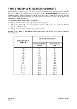
NOTE:
Grease lip seals before
assembly.
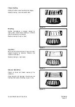
CLEANING AND INSPECTION
GENERAL GUIDELINES
All parts must be clean to permit an effective inspection. During assembly, it is very important that no dirt or
foreign material enters unit being assembled. Even minute particles can cause malfunction of close fitting
parts such as thrust bearing, matched parts, etc.
1.
Clean all metal parts thoroughly using a suitable cleaning fluid. It is recommended that parts be
immersed in cleaning fluid and moved up and down slowly until all oils, lubricants, and/or foreign
materials are dissolved and parts are thoroughly clean.
2.
For bearings that can be removed, soak them in a suitable cleaning fluid for a minute or two, then
remove bearings from cleaning fluid and strike flat against a block of wood to dislodge solidified
particles of lubricant. Immerse again in cleaning fluid to flush out particles. Repeat above operation
until bearings are thoroughly clean. To dry bearings, use moisture-free compressed air. Be careful to
direct air stream across bearing to avoid spinning bearings that are not lubricated. DO NOT SPIN
BEARINGS WHEN DRYING; bearings may be rotated slowly by hand to facilitate drying process.
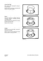
3.
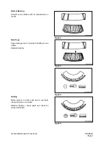
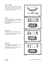
Carefully inspect all bearing rollers, cages and cups for wear, chipping or nicks to determine
condition. Do not replace a bearing cone or cup individually without replacing mating cup or cone at
the same time. After inspection, dip bearings in light weight oil and wrap in clean lintless cloth or
paper to protect them until installation.
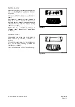
For those bearings that are to be inspected in place; inspect bearings for roughness of rotation,
scoring, pitting, cracked or chipped races. If any of these defects are found, replace bearings. Also
inspect defective bearing housing and/or shaft for grooved, galled or burred conditions that indicate
bearing has been turning in its housing or on its shaft.
4.
It is more economical to replace oil seals, O-rings, sealing rings, gaskets and snap rings when unit is
disassembled than waiting for premature failures; refer to latest Micro Fiche and/or Parts Book for
replacement items. Be extremely careful when installing sealing members, to avoid cutting or
WARNING!
Care should be exercised to avoid inhalation of vapors, exposure to skin and creating fire
hazards when using solvent type cleaners.
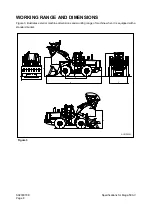
Figure 1
Summary of Contents for Mega 500-V
Page 4: ...1SAFETY ...
Page 41: ...1SPECIFICATIONS ...
Page 47: ...S0203070K Page 6 Specifications for Mega 500 V ENGINE PERFORMANCE CURVES AHS3720L Figure 2 ...
Page 55: ...S0203070K Page 14 Specifications for Mega 500 V ...
Page 56: ...1GENERAL MAINTENANCE ...
Page 70: ...S0302000 Page 14 General Maintenance Procedures Return to Master Table of Contents ...
Page 83: ...1UPPER STRUCTURE ...
Page 85: ...S0403040K Page 2 Counterweight TABLE OF CONTENTS Specifications 3 Counterweight 3 ...
Page 87: ...S0403040K Page 4 Counterweight ...
Page 98: ...1LOWER STRUCTURE AND CHASSIS ...
Page 104: ...S0502020K Page 6 Center Joint Articulation Joint ...
Page 105: ...1ENGINE AND DRIVE TRAIN ...
Page 118: ...S0602170K Page 13 Axle ZF AP 420R Figure 9 ...
Page 119: ...S0602170K Page 14 Axle ZF AP 420R ...
Page 121: ...S0602170K Page 16 Axle ZF AP 420R FINAL DRIVE AP 407 409 Figure 10 ...
Page 123: ...S0602170K Page 18 Axle ZF AP 420R AP 411 415 Figure 11 ...
Page 125: ...S0602170K Page 20 Axle ZF AP 420R AP 417 420 Figure 12 ...
Page 129: ...S0602170K Page 24 Axle ZF AP 420R Differential Carrier RK Figure 14 ...
Page 131: ...S0602170K Page 26 Axle ZF AP 420R Differential Carrier DK ...
Page 135: ...S0602170K Page 30 Axle ZF AP 420R Differential Carrier HK Figure 16 ...
Page 178: ...S0602170K Page 73 Axle ZF AP 420R ILLUSTRATED TABLE Figure 152 ...
Page 194: ...S0602170K Page 89 Axle ZF AP 420R ILLUSTRATED TABLE Figure 196 ...
Page 210: ...S0602170K Page 105 Axle ZF AP 420R ILLUSTRATED TABLE Figure 242 ...
Page 225: ...S0602170K Page 120 Axle ZF AP 420R ILLUSTRATED TABLE Figure 289 ...
Page 251: ...S0605050K Page 26 Air Conditioner Return to Master Table of Contents ...
Page 261: ...S0607080K Page 10 Transmission and Torque Converter ZF 4WG 310 Figure 2 ...
Page 264: ...S0607080K Page 13 Transmission and Torque Converter ZF 4WG 310 ...
Page 271: ...S0607080K Page 20 Transmission and Torque Converter ZF 4WG 310 ...
Page 296: ...S0607080K Page 45 Transmission and Torque Converter ZF 4WG 310 ...
Page 447: ...S0607900C Page 36 Transmission Error Codes ZF ...
Page 448: ...1HYDRAULICS ...
Page 478: ...S0705010 Page 22 Cylinders Return to Master Table of Contents ...
Page 489: ...S0708460K Page 11 Main Pump Denison T6DMY Series ...
Page 490: ...S0708460K Page 12 Main Pump Denison T6DMY Series PARTS LIST Figure 8 ...
Page 504: ...S0708460K Page 26 Main Pump Denison T6DMY Series ...
Page 508: ...S0708470K Page 4 Steering and Brake Pump Denison T67DB Series PARTS LIST Figure 2 ...
Page 514: ...S0708470K Page 10 Steering and Brake Pump Denison T67DB Series DISASSEMBLY Figure 5 ...
Page 521: ...S0708470K Page 17 Steering and Brake Pump Denison T67DB Series ...
Page 522: ...S0708470K Page 18 Steering and Brake Pump Denison T67DB Series REASSEMBLY Figure 15 ...
Page 528: ...S0708470K Page 24 Steering and Brake Pump Denison T67DB Series ...
Page 548: ...S0709476K Page 2 Pilot Control Valve Return to Master Table of Contents ...
Page 554: ...S0709476K Page 8 Pilot Control Valve Return to Master Table of Contents ...
Page 557: ...S0709665K Page 3 Flow Amplifier Danfoss GENERAL DESCRIPTION Figure 1 ...
Page 558: ...S0709665K Page 4 Flow Amplifier Danfoss PARTS LIST Figure 2 ...
Page 609: ...S0709730K Page 7 Power Steering Unit Return to Master Table of Contents ...
Page 632: ...S0709730K Page 30 Power Steering Unit Return to Master Table of Contents ...
Page 638: ...S0709750K Page 6 Restriction Valve Return to Master Table of Contents ...
Page 644: ...S0793060K Page 6 Hydraulic Schematic Mega 500 V Return to Master Table of Contents ...
Page 645: ...1ELECTRICAL SYSTEM ...
Page 654: ...S0802190K Page 9 Electrical System Return to Master Table of Contents ...
Page 658: ...S0802190K Page 13 Electrical System Return to Master Table of Contents ...
Page 676: ...S0802190K Page 31 Electrical System Return to Master Table of Contents ...
Page 685: ...S0893060K Page 6 Electrical Schematic Mega 500 V Return to Master Table of Contents ...
Page 686: ...1ATTACHMENTS ...


