


S0309000
Page 11
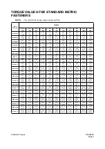
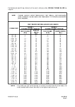
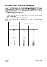
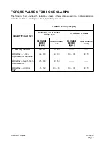
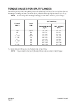
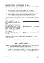
Standard Torques
Return to Master Table of Contents
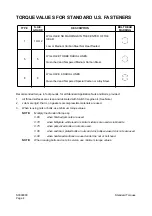
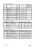
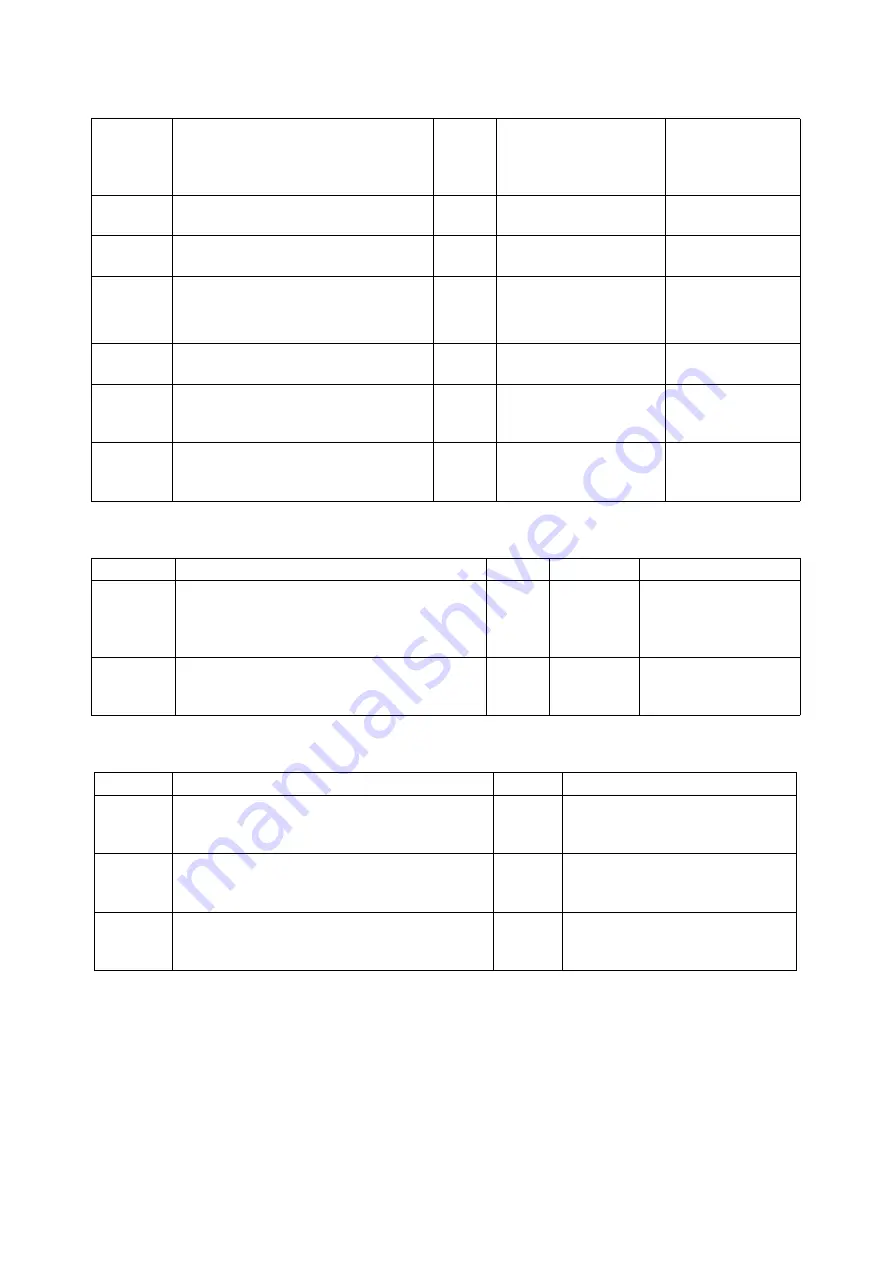
I. "Loctite" Fastener Adhesives
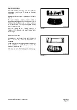
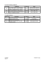
II. "Loctite" Pipe Thread Sealant
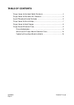
III. "Loctite" gasket/flange sealer
Product
Application
Color
Removal
Break-away
Cure Strength
(in lb) Of Sealer
Alone
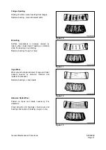
222
Low strength for 6 mm (1/4") or
smaller fasteners.
Purple
Hand tools
45
242 or
243
Medium strength for 6 mm (1/4") and
larger fasteners.
Blue
Hand tools
80
262
High strength for high grade
fasteners subject to shock, stress
and vibration.
Red
Heat/260°C (500°F)
Remove HOT
(NO solvent)
160
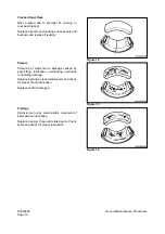
271
Extra high strength for fine thread
fasteners up to 25 mm (1") diameter.
Red
Heat/260°C (500°F)
Remove HOT
160
272
High temperature/high strength for
hostile environments to 232°C
(450°F).
Red
Heat/316°C (600°F)
Remove HOT
180
277
Extra high strength for coarse thread
fasteners 25 mm (1") diameter and
larger.
Red
Heat/260°C (500°F)
Remove HOT
210
Product
Application
Color
Removal
Required Setup
545
"No-filler/non-clog" formula for high-
pressure hydraulic systems. Over-
application will not restrict or foul system
components.
Purple
Hand tools
4 Hours (or 1/2 hour
with Locquic "T"
Primer)
656
Solvent-resistant, higher viscosity tapered
thread sealer.
White
Hand tools
4 Hours (or 1/2 hour
with Locquic "T"
Primer)
Product
Application
Color
Notes
518
Gasket eliminator specifically made for
aluminum flanges/surfaces. For hydraulic
systems to 34,475 kPa (5,000 psi).
Red
Use Locquic "N" primer for fast
(1/2 - 4 hours) setup. Unprimed
setup 4 - 24 hours.
504
Low pressure/wide-gap gasket eliminator
compound. Fills gaps to 0.0012 mm (0.030"),
cures to rigid seal.
Orange
Use Locquic "N" primer for
faster (1/2 - 4 hours) setup.
Unprimed setup 4 - 24 hours.
515
General purpose, fast setup, flexible-cure
gasket eliminator. For non-rigid assemblies
subject to shock, vibration or deflection.
Purple
Use Locquic "N" primer for
faster (1/4 - 2 hours) setup.
Unprimed setup 1 - 12 hours.
Summary of Contents for Mega 500-V
Page 4: ...1SAFETY ...
Page 41: ...1SPECIFICATIONS ...
Page 47: ...S0203070K Page 6 Specifications for Mega 500 V ENGINE PERFORMANCE CURVES AHS3720L Figure 2 ...
Page 55: ...S0203070K Page 14 Specifications for Mega 500 V ...
Page 56: ...1GENERAL MAINTENANCE ...
Page 70: ...S0302000 Page 14 General Maintenance Procedures Return to Master Table of Contents ...
Page 83: ...1UPPER STRUCTURE ...
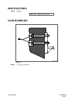
Page 85: ...S0403040K Page 2 Counterweight TABLE OF CONTENTS Specifications 3 Counterweight 3 ...
Page 87: ...S0403040K Page 4 Counterweight ...
Page 98: ...1LOWER STRUCTURE AND CHASSIS ...
Page 104: ...S0502020K Page 6 Center Joint Articulation Joint ...
Page 105: ...1ENGINE AND DRIVE TRAIN ...
Page 118: ...S0602170K Page 13 Axle ZF AP 420R Figure 9 ...
Page 119: ...S0602170K Page 14 Axle ZF AP 420R ...
Page 121: ...S0602170K Page 16 Axle ZF AP 420R FINAL DRIVE AP 407 409 Figure 10 ...
Page 123: ...S0602170K Page 18 Axle ZF AP 420R AP 411 415 Figure 11 ...
Page 125: ...S0602170K Page 20 Axle ZF AP 420R AP 417 420 Figure 12 ...
Page 129: ...S0602170K Page 24 Axle ZF AP 420R Differential Carrier RK Figure 14 ...
Page 131: ...S0602170K Page 26 Axle ZF AP 420R Differential Carrier DK ...
Page 135: ...S0602170K Page 30 Axle ZF AP 420R Differential Carrier HK Figure 16 ...
Page 178: ...S0602170K Page 73 Axle ZF AP 420R ILLUSTRATED TABLE Figure 152 ...
Page 194: ...S0602170K Page 89 Axle ZF AP 420R ILLUSTRATED TABLE Figure 196 ...
Page 210: ...S0602170K Page 105 Axle ZF AP 420R ILLUSTRATED TABLE Figure 242 ...
Page 225: ...S0602170K Page 120 Axle ZF AP 420R ILLUSTRATED TABLE Figure 289 ...
Page 251: ...S0605050K Page 26 Air Conditioner Return to Master Table of Contents ...
Page 261: ...S0607080K Page 10 Transmission and Torque Converter ZF 4WG 310 Figure 2 ...
Page 264: ...S0607080K Page 13 Transmission and Torque Converter ZF 4WG 310 ...
Page 271: ...S0607080K Page 20 Transmission and Torque Converter ZF 4WG 310 ...
Page 296: ...S0607080K Page 45 Transmission and Torque Converter ZF 4WG 310 ...
Page 447: ...S0607900C Page 36 Transmission Error Codes ZF ...
Page 448: ...1HYDRAULICS ...
Page 478: ...S0705010 Page 22 Cylinders Return to Master Table of Contents ...
Page 489: ...S0708460K Page 11 Main Pump Denison T6DMY Series ...
Page 490: ...S0708460K Page 12 Main Pump Denison T6DMY Series PARTS LIST Figure 8 ...
Page 504: ...S0708460K Page 26 Main Pump Denison T6DMY Series ...
Page 508: ...S0708470K Page 4 Steering and Brake Pump Denison T67DB Series PARTS LIST Figure 2 ...
Page 514: ...S0708470K Page 10 Steering and Brake Pump Denison T67DB Series DISASSEMBLY Figure 5 ...
Page 521: ...S0708470K Page 17 Steering and Brake Pump Denison T67DB Series ...
Page 522: ...S0708470K Page 18 Steering and Brake Pump Denison T67DB Series REASSEMBLY Figure 15 ...
Page 528: ...S0708470K Page 24 Steering and Brake Pump Denison T67DB Series ...
Page 548: ...S0709476K Page 2 Pilot Control Valve Return to Master Table of Contents ...
Page 554: ...S0709476K Page 8 Pilot Control Valve Return to Master Table of Contents ...
Page 557: ...S0709665K Page 3 Flow Amplifier Danfoss GENERAL DESCRIPTION Figure 1 ...
Page 558: ...S0709665K Page 4 Flow Amplifier Danfoss PARTS LIST Figure 2 ...
Page 609: ...S0709730K Page 7 Power Steering Unit Return to Master Table of Contents ...
Page 632: ...S0709730K Page 30 Power Steering Unit Return to Master Table of Contents ...
Page 638: ...S0709750K Page 6 Restriction Valve Return to Master Table of Contents ...
Page 644: ...S0793060K Page 6 Hydraulic Schematic Mega 500 V Return to Master Table of Contents ...
Page 645: ...1ELECTRICAL SYSTEM ...
Page 654: ...S0802190K Page 9 Electrical System Return to Master Table of Contents ...
Page 658: ...S0802190K Page 13 Electrical System Return to Master Table of Contents ...
Page 676: ...S0802190K Page 31 Electrical System Return to Master Table of Contents ...
Page 685: ...S0893060K Page 6 Electrical Schematic Mega 500 V Return to Master Table of Contents ...
Page 686: ...1ATTACHMENTS ...


