S0102000
Page 11
Track Excavator Safety
FUEL, OIL AND HYDRAULIC FLUID FIRE
HAZARDS
Fuel, oil and antifreeze will catch fire if it is
brought close to a flame. Fuel is particularly
flammable and can be hazardous.
Always strictly observe the following.
Add fuel, oil, antifreeze and hydraulic fluid to the
machine only in a well-ventilated area. The
machine must be parked with controls, lights
and switches turned "OFF." The engine must be
"OFF" and any flames, glowing embers,
auxiliary heating units or spark-causing
equipment must be doused, turned off and/or
kept well clear of the machine.
Static electricity can produce dangerous sparks
at the fuel filling nozzle. In very cold, dry
weather or other conditions that could produce a
static discharge, keep the tip of the fuel nozzle
in constant contact with the neck of the fuel
filling nozzle, to provide a ground.
Keep fuel and other fluid reservoir caps tight and
do not start the engine until caps have been
secured.
PRECAUTIONS WHEN HANDLING FLUIDS
AT HIGH TEMPERATURE
Immediately after operations are stopped, the
coolant, engine oil, and hydraulic oil are at high
temperature and the radiator and hydraulic tank
are still under pressure. Attempting to remove
the cap, drain the oil or coolant, or replace the
filters may lead to serious burns. Always wait for
the temperature to go down, and follow the
specified procedures when carrying out these
operations.
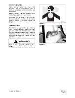
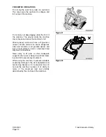
To prevent hot coolant from spurting out, shut
down engine, wait for the coolant to cool, then
loosen the cap slowly to relieve the pressure.
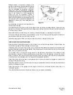
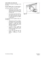
To prevent hot oil from spurting out, shut down
engine, wait for the oil to cool, then loosen the
cap slowly to relieve the pressure.
Figure 3
HAOA050L
Figure 4
HAOA060L
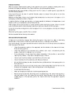
Figure 5
Summary of Contents for Solar 225LC-V
Page 2: ......
Page 4: ......
Page 7: ...1SAFETY ...
Page 8: ......
Page 46: ...S0102000 Page 38 Track Excavator Safety ...
Page 47: ...1SPECIFICATIONS ...
Page 48: ......
Page 54: ...S0205015K Page 6 Specifications for Solar 225LC V Return to Master Table of Contents ...
Page 70: ...S0205015K Page 22 Specifications for Solar 225LC V Return to Master Table of Contents ...
Page 71: ...1GENERAL MAINTENANCE ...
Page 72: ......
Page 86: ...S0302000 Page 14 General Maintenance Procedures ...
Page 99: ...1UPPER STRUCTURE ...
Page 100: ......
Page 102: ...S0402040K Page 2 Cab TABLE OF CONTENTS Removal 3 Installation 6 ...
Page 116: ...S0403050K Page 8 Counterweight Return to Master Table of Contents ...
Page 140: ...S0407000 Page 6 Swing Bearing ...
Page 165: ...1LOWER STRUCTURE AND CHASSIS ...
Page 166: ......
Page 192: ...S0505030 Page 26 Track Assembly Return to Master Table of Contents ...
Page 193: ...1ENGINE AND DRIVE TRAIN ...
Page 194: ......
Page 205: ...S0605060K Page 11 Air Conditioner Face and Defroster ARS1300L Figure 12 ...
Page 229: ...S0609000 Page 9 Drive Coupling Main Pump Figure 10 DRIVE COUPLING INSTALLATION UCHIDA PUMP ...
Page 234: ...S0609000 Page 14 Drive Coupling Main Pump ...
Page 235: ...1HYDRAULICS ...
Page 236: ......
Page 249: ...S0702170K Page 13 Hydraulic System Troubleshooting Testing and Adjustment ...
Page 272: ...S0702170K Page 36 Hydraulic System Troubleshooting Testing and Adjustment ...
Page 274: ...S0703010K Page 2 Accumulator TABLE OF CONTENTS General Description 3 Specifications 4 ...
Page 297: ...S0705000 Page 9 Cylinders ...
Page 301: ...S0705000 Page 13 Cylinders ...
Page 311: ...S0705000 Page 23 Cylinders ...
Page 315: ...S0705000 Page 27 Cylinders ...
Page 324: ...S0705000 Page 36 Cylinders 17 Force out pin bushing 1 from body of cylinder Figure 28 ...
Page 328: ...S0705000 Page 40 Cylinders ...
Page 335: ...S0707200 Page 7 Swing Motor Return to Master Table of Contents ...
Page 341: ...S0707200 Page 13 Swing Motor Return to Master Table of Contents SPECIAL TOOLS Figure 6 ...
Page 358: ...S0707200 Page 30 Swing Motor Return to Master Table of Contents ...
Page 452: ...S0708320 Page 40 Main Pump With Regulator Return to Master Table of Contents ...
Page 458: ...S0709401K Page 6 Main Control Valve Kayaba Figure 1 ...
Page 459: ...S0709401K Page 7 Main Control Valve Kayaba Figure 2 ...
Page 461: ...S0709401K Page 9 Main Control Valve Kayaba ...
Page 463: ...S0709401K Page 11 Main Control Valve Kayaba Figure 4 ...
Page 475: ...S0709401K Page 23 Main Control Valve Kayaba Figure 16 ...
Page 508: ...S0709401K Page 56 Main Control Valve Kayaba Figure 54 ...
Page 563: ...1ELECTRICAL SYSTEM ...
Page 564: ......
Page 618: ...S0802220K Page 54 Electrical System ...
Page 637: ...S0802220K Page 73 Electrical System ...
Page 649: ...1ATTACHMENTS ...
Page 650: ......
Page 670: ......


