S0102000
Page 32
Track Excavator Safety
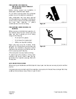
ACTION WHEN ABNORMALLY IS FOUND DURING INSPECTION
If any abnormality is found during inspection, always carry out repairs. In particular, if the machine is used
when there are still problems with the brake or work equipment systems, it may lead to serious injury.
If necessary depending on the type of failure, please contact your Daewoo distributor for repairs.
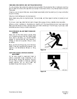
PRECAUTIONS WITH HIGH PRESSURE LINE, TUBES AND HOSES
When inspecting or replacing high-pressure piping or hoses, check that the pressure has been released
from the circuit. Failure to release the pressure may lead to serious injury. Always do the following;
•
Wear protective glasses and leather gloves.
•
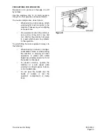
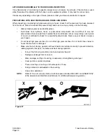
Fluid leaks from hydraulic hoses or pressurized components can be difficult to see but
pressurized oil has enough force to pierce the skin and cause serious injury. Always use a piece
of wood or cardboard to check for suspected hydraulic leaks. Never use your hands or expose
your fingers.
•
Do not bend high pressure lines. Do not strike high pressure lines. Do not install lines, tubes or
hoses that are bent or damaged.
•
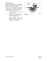
Make sure that all clamps, guards and heat shields are installed correctly to prevent vibration,
rubbing against other parts, and excessive heat during operation.
–
If any of the following conditions are found, replace the part.
–
Damage or leakage from hose end.
–
Wear, damage, cutting of covering, or exposure of strengthening wire layer.
–
Cover portion is swollen in places.
–
There is twisting or crushing at movable parts of hose.
–
Foreign material is embedded in the covering.
–
Hose end is deformed.
NOTE:
Refer to "Hose In-service Lifetime Limit (European Standard ISO 8331 and EN982 CEN)"
in the Operation and Maintenance Manual, for additional European regulations.
HAOA420L
O
X
X
Figure 37
Summary of Contents for Solar 225LC-V
Page 2: ......
Page 4: ......
Page 7: ...1SAFETY ...
Page 8: ......
Page 46: ...S0102000 Page 38 Track Excavator Safety ...
Page 47: ...1SPECIFICATIONS ...
Page 48: ......
Page 54: ...S0205015K Page 6 Specifications for Solar 225LC V Return to Master Table of Contents ...
Page 70: ...S0205015K Page 22 Specifications for Solar 225LC V Return to Master Table of Contents ...
Page 71: ...1GENERAL MAINTENANCE ...
Page 72: ......
Page 86: ...S0302000 Page 14 General Maintenance Procedures ...
Page 99: ...1UPPER STRUCTURE ...
Page 100: ......
Page 102: ...S0402040K Page 2 Cab TABLE OF CONTENTS Removal 3 Installation 6 ...
Page 116: ...S0403050K Page 8 Counterweight Return to Master Table of Contents ...
Page 140: ...S0407000 Page 6 Swing Bearing ...
Page 165: ...1LOWER STRUCTURE AND CHASSIS ...
Page 166: ......
Page 192: ...S0505030 Page 26 Track Assembly Return to Master Table of Contents ...
Page 193: ...1ENGINE AND DRIVE TRAIN ...
Page 194: ......
Page 205: ...S0605060K Page 11 Air Conditioner Face and Defroster ARS1300L Figure 12 ...
Page 229: ...S0609000 Page 9 Drive Coupling Main Pump Figure 10 DRIVE COUPLING INSTALLATION UCHIDA PUMP ...
Page 234: ...S0609000 Page 14 Drive Coupling Main Pump ...
Page 235: ...1HYDRAULICS ...
Page 236: ......
Page 249: ...S0702170K Page 13 Hydraulic System Troubleshooting Testing and Adjustment ...
Page 272: ...S0702170K Page 36 Hydraulic System Troubleshooting Testing and Adjustment ...
Page 274: ...S0703010K Page 2 Accumulator TABLE OF CONTENTS General Description 3 Specifications 4 ...
Page 297: ...S0705000 Page 9 Cylinders ...
Page 301: ...S0705000 Page 13 Cylinders ...
Page 311: ...S0705000 Page 23 Cylinders ...
Page 315: ...S0705000 Page 27 Cylinders ...
Page 324: ...S0705000 Page 36 Cylinders 17 Force out pin bushing 1 from body of cylinder Figure 28 ...
Page 328: ...S0705000 Page 40 Cylinders ...
Page 335: ...S0707200 Page 7 Swing Motor Return to Master Table of Contents ...
Page 341: ...S0707200 Page 13 Swing Motor Return to Master Table of Contents SPECIAL TOOLS Figure 6 ...
Page 358: ...S0707200 Page 30 Swing Motor Return to Master Table of Contents ...
Page 452: ...S0708320 Page 40 Main Pump With Regulator Return to Master Table of Contents ...
Page 458: ...S0709401K Page 6 Main Control Valve Kayaba Figure 1 ...
Page 459: ...S0709401K Page 7 Main Control Valve Kayaba Figure 2 ...
Page 461: ...S0709401K Page 9 Main Control Valve Kayaba ...
Page 463: ...S0709401K Page 11 Main Control Valve Kayaba Figure 4 ...
Page 475: ...S0709401K Page 23 Main Control Valve Kayaba Figure 16 ...
Page 508: ...S0709401K Page 56 Main Control Valve Kayaba Figure 54 ...
Page 563: ...1ELECTRICAL SYSTEM ...
Page 564: ......
Page 618: ...S0802220K Page 54 Electrical System ...
Page 637: ...S0802220K Page 73 Electrical System ...
Page 649: ...1ATTACHMENTS ...
Page 650: ......
Page 670: ......

