S0205015K
Page 19
Specifications for Solar 225LC-V
Return to Master Table of Contents
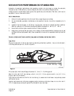
Rotate the turntable 180°. Both tests should be repeated three times. Average all results to obtain a final
value.
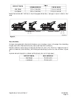
Travel Deviation
To check steering deviation (travel motor balance), use a long tape or rope, or the edge of an undeviating
straight road curb or other marker to verify side-to-side travel motor uniformity.
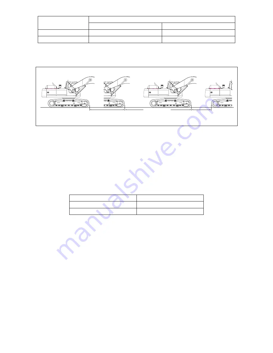
Deviation distance should always be measured at the 20 m (65' 7-1/2") "finish line." Repeat the test in
reverse to measure in both directions, with starting point becoming the finish line, and vice versa. (Figure
6)
A greater amount of deviation is allowed with the travel control set for high speed.
RATE OF TRAVEL
TIME
STANDARD MODE
POWER MODE
High Speed
13.5 ±1.0 seconds
12.5 ±1.0 seconds
Low Speed
23.5 ±1.5 seconds
22.5 ±1.5 seconds
RATE OF TRAVEL
MAX. DISTANCE
High Speed
150 mm (6 in)
Low Speed
150 mm (6 in)
ARS1500L
3m - 5m
(10' - 15')
3m - 5m
(10' - 15')
20 m (65' 7-1/2")
Figure 6
Summary of Contents for Solar 225LC-V
Page 2: ......
Page 4: ......
Page 7: ...1SAFETY ...
Page 8: ......
Page 46: ...S0102000 Page 38 Track Excavator Safety ...
Page 47: ...1SPECIFICATIONS ...
Page 48: ......
Page 54: ...S0205015K Page 6 Specifications for Solar 225LC V Return to Master Table of Contents ...
Page 70: ...S0205015K Page 22 Specifications for Solar 225LC V Return to Master Table of Contents ...
Page 71: ...1GENERAL MAINTENANCE ...
Page 72: ......
Page 86: ...S0302000 Page 14 General Maintenance Procedures ...
Page 99: ...1UPPER STRUCTURE ...
Page 100: ......
Page 102: ...S0402040K Page 2 Cab TABLE OF CONTENTS Removal 3 Installation 6 ...
Page 116: ...S0403050K Page 8 Counterweight Return to Master Table of Contents ...
Page 140: ...S0407000 Page 6 Swing Bearing ...
Page 165: ...1LOWER STRUCTURE AND CHASSIS ...
Page 166: ......
Page 192: ...S0505030 Page 26 Track Assembly Return to Master Table of Contents ...
Page 193: ...1ENGINE AND DRIVE TRAIN ...
Page 194: ......
Page 205: ...S0605060K Page 11 Air Conditioner Face and Defroster ARS1300L Figure 12 ...
Page 229: ...S0609000 Page 9 Drive Coupling Main Pump Figure 10 DRIVE COUPLING INSTALLATION UCHIDA PUMP ...
Page 234: ...S0609000 Page 14 Drive Coupling Main Pump ...
Page 235: ...1HYDRAULICS ...
Page 236: ......
Page 249: ...S0702170K Page 13 Hydraulic System Troubleshooting Testing and Adjustment ...
Page 272: ...S0702170K Page 36 Hydraulic System Troubleshooting Testing and Adjustment ...
Page 274: ...S0703010K Page 2 Accumulator TABLE OF CONTENTS General Description 3 Specifications 4 ...
Page 297: ...S0705000 Page 9 Cylinders ...
Page 301: ...S0705000 Page 13 Cylinders ...
Page 311: ...S0705000 Page 23 Cylinders ...
Page 315: ...S0705000 Page 27 Cylinders ...
Page 324: ...S0705000 Page 36 Cylinders 17 Force out pin bushing 1 from body of cylinder Figure 28 ...
Page 328: ...S0705000 Page 40 Cylinders ...
Page 335: ...S0707200 Page 7 Swing Motor Return to Master Table of Contents ...
Page 341: ...S0707200 Page 13 Swing Motor Return to Master Table of Contents SPECIAL TOOLS Figure 6 ...
Page 358: ...S0707200 Page 30 Swing Motor Return to Master Table of Contents ...
Page 452: ...S0708320 Page 40 Main Pump With Regulator Return to Master Table of Contents ...
Page 458: ...S0709401K Page 6 Main Control Valve Kayaba Figure 1 ...
Page 459: ...S0709401K Page 7 Main Control Valve Kayaba Figure 2 ...
Page 461: ...S0709401K Page 9 Main Control Valve Kayaba ...
Page 463: ...S0709401K Page 11 Main Control Valve Kayaba Figure 4 ...
Page 475: ...S0709401K Page 23 Main Control Valve Kayaba Figure 16 ...
Page 508: ...S0709401K Page 56 Main Control Valve Kayaba Figure 54 ...
Page 563: ...1ELECTRICAL SYSTEM ...
Page 564: ......
Page 618: ...S0802220K Page 54 Electrical System ...
Page 637: ...S0802220K Page 73 Electrical System ...
Page 649: ...1ATTACHMENTS ...
Page 650: ......
Page 670: ......

