S0302000
Page 4
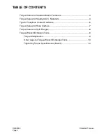
General Maintenance Procedures
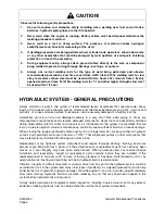
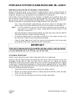
HYDRAULIC SYSTEM - GENERAL PRECAUTIONS
Always maintain oil level in the system at recommended levels. Assemblies that operate under heavy
loads, at high speed, with extremely precise dimensional tolerances between moving parts - pistons and
cylinders, or shoes and swash plates, for example - can be severely damaged if oil supply runs dry.
Assemblies can be run dry and damaged severely in a very short time when piping or hoses are
disconnected to repair leaks and/or replace damaged components. Hoses that are inadvertently switched
during disassembly (inlet for outlet and vice versa), air introduced into the system or assemblies that are
low on oil due to neglect or careless maintenance, could all produce sufficient fluid loss to cause damage.
When starting the engine (particularly after long layoff or storage intervals), make sure that all hydraulic
controls and operating circuits are in neutral, or "OFF." That will prevent pumps or other components that
may be temporarily oil-starved from being run under a load.
Replacement of any hydraulic system component could require thorough cleaning, flushing, and some
amount of pre-filling with fresh, clean oil if the protective seal on replacement parts has obviously been
broken or if seal integrity may have been compromised. When protective seals are removed before
installation and reassembly, inspect all replacement parts carefully, before they are installed. If the
replacement part is bone dry (with no trace of factory pre-lube) or has been contaminated by dirt or by
questionable oils, flushing and pre-filling with clean hydraulic fluid is recommended.
Vibration, irregular or difficult movement or unusual noise from any part of the hydraulic system could be
an indication of air in the system (and many other types of problems). As a general precaution (and to help
minimize the risk of potential long-term damage), allow the engine to run at no-load idle speed immediately
after initial start-up. Hydraulic fluid will circulate, releasing any air that may have been trapped in the
system before load demands are imposed.
A daily walk-around pre-start equipment safety inspection, including a quick visual scan for any exterior
evidence of leaking hydraulic fluid, can help extend the service life of system components.
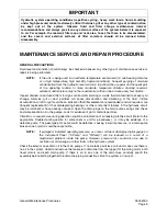
CAUTION!
Observe the following safety precautions:
1.
Use extra caution and adequate safety shielding when welding near fuel and oil tanks,
batteries, hydraulic piping lines or other fire hazards.
2.
Never weld when the engine is running. Battery cables must be disconnected before the
welding procedure is started.
3.
Never weld on a wet or damp surface. The presence of moisture causes hydrogen
embrittlement and structural weakening of the weld.
4.
If welding procedures are being performed near cylinder rods, operator’s cab window areas
or any other assemblies that could be damaged by weld spatters, use adequate shielding
protection in front of the assembly.
5.
During equipment setup, always attach ground cables directly to the area or component
being welded to prevent arcing through bearings, bushings, or spacers.
6.
Always use correct welding rods for the type of weld being performed and observe
recommended precautions and time constraints. AWS Class E7018 welding rods for low
alloy to medium carbon steel must be used within two hours after removal from a freshly
opened container. Class E11018G welding rods for T-1 and other higher strength steel must
be used within 1/2 hour.
Summary of Contents for Solar 225LC-V
Page 2: ......
Page 4: ......
Page 7: ...1SAFETY ...
Page 8: ......
Page 46: ...S0102000 Page 38 Track Excavator Safety ...
Page 47: ...1SPECIFICATIONS ...
Page 48: ......
Page 54: ...S0205015K Page 6 Specifications for Solar 225LC V Return to Master Table of Contents ...
Page 70: ...S0205015K Page 22 Specifications for Solar 225LC V Return to Master Table of Contents ...
Page 71: ...1GENERAL MAINTENANCE ...
Page 72: ......
Page 86: ...S0302000 Page 14 General Maintenance Procedures ...
Page 99: ...1UPPER STRUCTURE ...
Page 100: ......
Page 102: ...S0402040K Page 2 Cab TABLE OF CONTENTS Removal 3 Installation 6 ...
Page 116: ...S0403050K Page 8 Counterweight Return to Master Table of Contents ...
Page 140: ...S0407000 Page 6 Swing Bearing ...
Page 165: ...1LOWER STRUCTURE AND CHASSIS ...
Page 166: ......
Page 192: ...S0505030 Page 26 Track Assembly Return to Master Table of Contents ...
Page 193: ...1ENGINE AND DRIVE TRAIN ...
Page 194: ......
Page 205: ...S0605060K Page 11 Air Conditioner Face and Defroster ARS1300L Figure 12 ...
Page 229: ...S0609000 Page 9 Drive Coupling Main Pump Figure 10 DRIVE COUPLING INSTALLATION UCHIDA PUMP ...
Page 234: ...S0609000 Page 14 Drive Coupling Main Pump ...
Page 235: ...1HYDRAULICS ...
Page 236: ......
Page 249: ...S0702170K Page 13 Hydraulic System Troubleshooting Testing and Adjustment ...
Page 272: ...S0702170K Page 36 Hydraulic System Troubleshooting Testing and Adjustment ...
Page 274: ...S0703010K Page 2 Accumulator TABLE OF CONTENTS General Description 3 Specifications 4 ...
Page 297: ...S0705000 Page 9 Cylinders ...
Page 301: ...S0705000 Page 13 Cylinders ...
Page 311: ...S0705000 Page 23 Cylinders ...
Page 315: ...S0705000 Page 27 Cylinders ...
Page 324: ...S0705000 Page 36 Cylinders 17 Force out pin bushing 1 from body of cylinder Figure 28 ...
Page 328: ...S0705000 Page 40 Cylinders ...
Page 335: ...S0707200 Page 7 Swing Motor Return to Master Table of Contents ...
Page 341: ...S0707200 Page 13 Swing Motor Return to Master Table of Contents SPECIAL TOOLS Figure 6 ...
Page 358: ...S0707200 Page 30 Swing Motor Return to Master Table of Contents ...
Page 452: ...S0708320 Page 40 Main Pump With Regulator Return to Master Table of Contents ...
Page 458: ...S0709401K Page 6 Main Control Valve Kayaba Figure 1 ...
Page 459: ...S0709401K Page 7 Main Control Valve Kayaba Figure 2 ...
Page 461: ...S0709401K Page 9 Main Control Valve Kayaba ...
Page 463: ...S0709401K Page 11 Main Control Valve Kayaba Figure 4 ...
Page 475: ...S0709401K Page 23 Main Control Valve Kayaba Figure 16 ...
Page 508: ...S0709401K Page 56 Main Control Valve Kayaba Figure 54 ...
Page 563: ...1ELECTRICAL SYSTEM ...
Page 564: ......
Page 618: ...S0802220K Page 54 Electrical System ...
Page 637: ...S0802220K Page 73 Electrical System ...
Page 649: ...1ATTACHMENTS ...
Page 650: ......
Page 670: ......

