Page 18
Hydraulic System Troubleshooting, Testing and
Adjustment
Return to Master Table of Contents
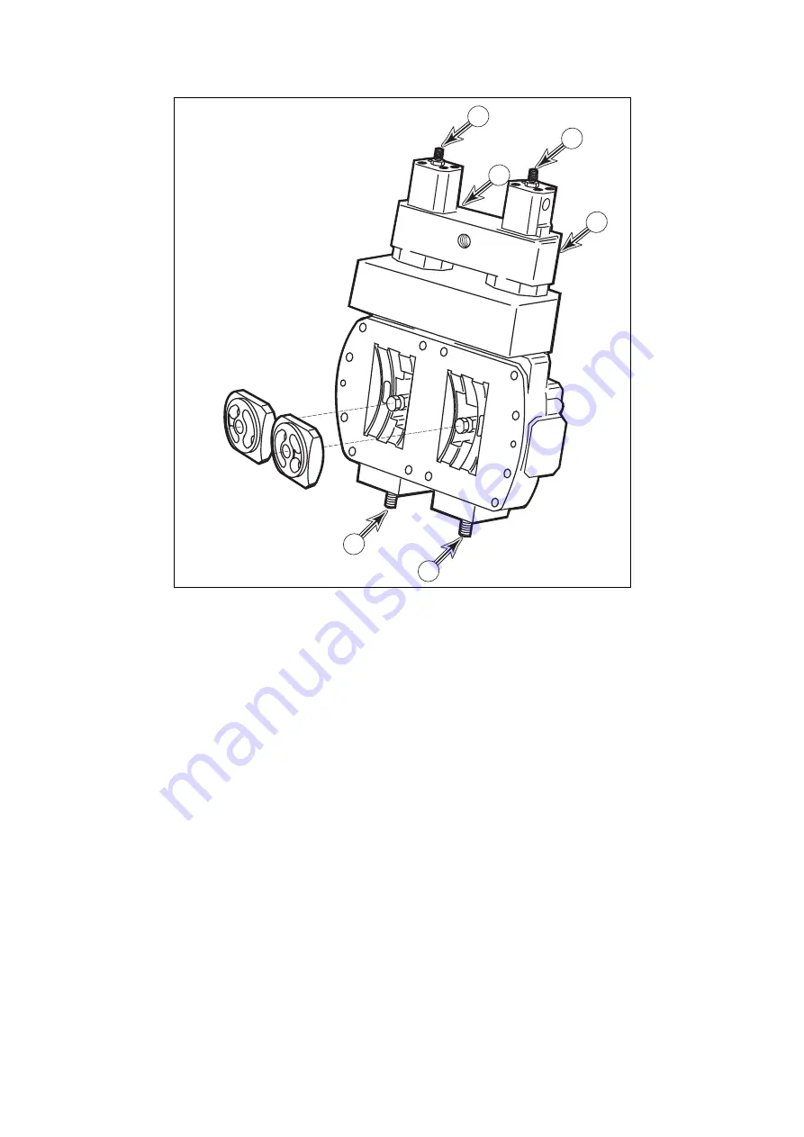
Refer to the illustration of the pump regulator control valve (Figure 12) for the location of adjustment screws
(1, 2 and 3). There are three different adjustments, Qmax, Pd-Q, adjustment screws (1, 2 and 3). Each one
of the adjustment procedures could affect the setting of the others.
Check and record the arm dump speed performance test before and after input power adjustment, whether
or not a flow meter is used.
NOTE:
Regulator adjustments affect total cumulative horsepower, since each regulator
compensates for the output of the other. It is not necessary to adjust both regulators at the
same time, but after checking or adjusting one of them, the remaining unit should also be
checked.
2
3
2
3
1
1
ASS0320L
Figure 12
Summary of Contents for Solar 420LC-V
Page 1: ...Return to Master Table of Contents 1HYDRAULICS...
Page 33: ...S0703010K Page 2 Accumulator TABLE OF CONTENTS General Description 3 Specifications 4...
Page 43: ...S0704090K Page 8 Center Joint Swivel...
Page 63: ...S0705000 Page 20 Cylinders Return to Master Table of Contents...
Page 70: ...S0707260 Page 7 Swing Motor...
Page 74: ...S0707260 Page 11 Swing Motor SPECIAL TOOLS Figure 5...
Page 91: ...S0707260 Page 28 Swing Motor...
Page 103: ...S0707365 Page 12 Travel Motor With Gearbox A6V160HD PARTS LIST Travel Motor Figure 12 HTS6331...
Page 107: ...S0707365 Page 16 Travel Motor With Gearbox A6V160HD Travel Motor Control HTS6331 Figure 14...
Page 136: ...S0707365 Page 45 Travel Motor With Gearbox A6V160HD 29 Remove gasket Figure 91 Figure 91 3061...


