Page 19
Hydraulic System Troubleshooting, Testing and
Adjustment
Return to Master Table of Contents
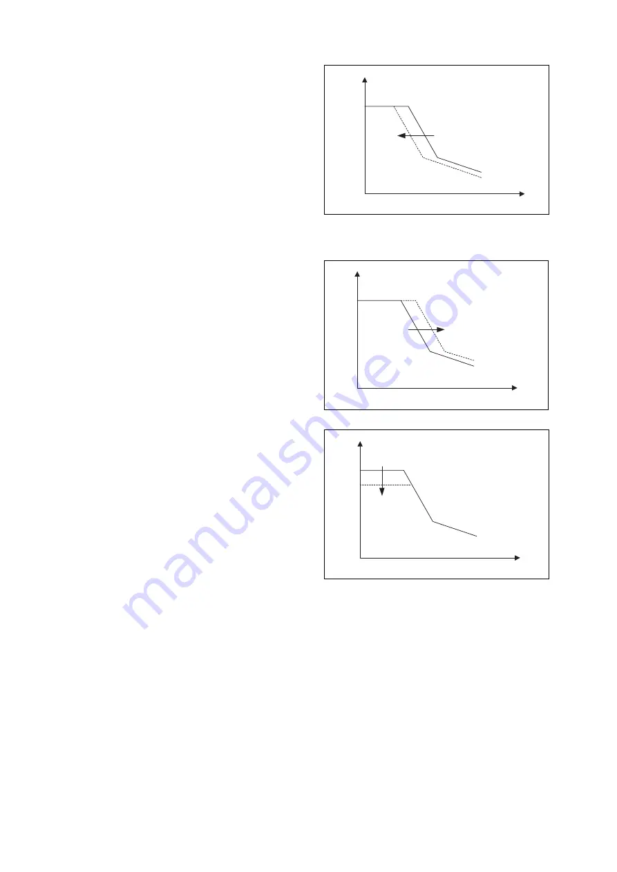
Start the engine and turn the engine speed dial
to maximum. When normal operating
temperature is reached, adjust screw 2
clockwise to shft the Pi-Q control valve curve
decrease componsating control pressure.
1/2 turn on the adjusting screw is equal to
approximately -0.7 kgf/cm
2
of Pi.
NOTE:
For each full turn of adjustment
on the screw (2), the square-
tipped adjusting screw should
be turned in the opposite
direction turns to avoid
changing inner spring
adjustment.
Pump input power adjustments are normally
made in small increments, 1/4 turn (90°) or less,
each time.
Turning the screw (3) clockwise shift Pd-Q
curves right and increase input horse power. 1/2
turn on the screw (3) is equal to approximately
+33 kgf/cm
2
of Pd.
The adjusting screw (1) affects the delivery rate
(Q) of the pump. Turning the adjusting screw
shift the maximum cut flow (as shown in Figure
15).
Balance both pumps for equal output.
Pi
Q
ATS0850L
Figure 13
Pd
Q
ATS0870L
Figure 14
P
Q
ATS0860L
Figure 15
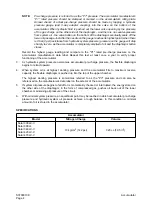
Summary of Contents for Solar 420LC-V
Page 1: ...Return to Master Table of Contents 1HYDRAULICS...
Page 33: ...S0703010K Page 2 Accumulator TABLE OF CONTENTS General Description 3 Specifications 4...
Page 43: ...S0704090K Page 8 Center Joint Swivel...
Page 63: ...S0705000 Page 20 Cylinders Return to Master Table of Contents...
Page 70: ...S0707260 Page 7 Swing Motor...
Page 74: ...S0707260 Page 11 Swing Motor SPECIAL TOOLS Figure 5...
Page 91: ...S0707260 Page 28 Swing Motor...
Page 103: ...S0707365 Page 12 Travel Motor With Gearbox A6V160HD PARTS LIST Travel Motor Figure 12 HTS6331...
Page 107: ...S0707365 Page 16 Travel Motor With Gearbox A6V160HD Travel Motor Control HTS6331 Figure 14...
Page 136: ...S0707365 Page 45 Travel Motor With Gearbox A6V160HD 29 Remove gasket Figure 91 Figure 91 3061...


