S0802220K
Page 62
Electrical System
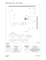
POWER BOOST CONTROL - CIRCUIT DIAGRAM
TERMINAL NO
12
16 15
(CN2)
7
6
18
17
4
(CN4)
14
13
8
TxD
CN7
5
TxD
3
2
4
1
RxD
RxD
10
19
20
9
10A
5
17
7
21
9
20
10
1
3
2
11
9
10
9
8
11
10
9
(CN3)
11
12
13
14
17
(CN1)
6
7
8
6
3
4
1
2
20
11
16
(CN7)
CN1-1
CN4
1
3
10
7
8
9
CN1
CN3-11
CN3-12
CN3-8
CN3-10
CN3-9
RxD
RxD
RS-422
TxD
TxD
5
6
1
CN2-3
7
6
CN1-13
CN1-9
CN1-2
CN1-8
4
1
3
20A
2
ARS1150L
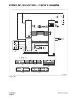
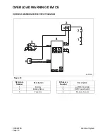
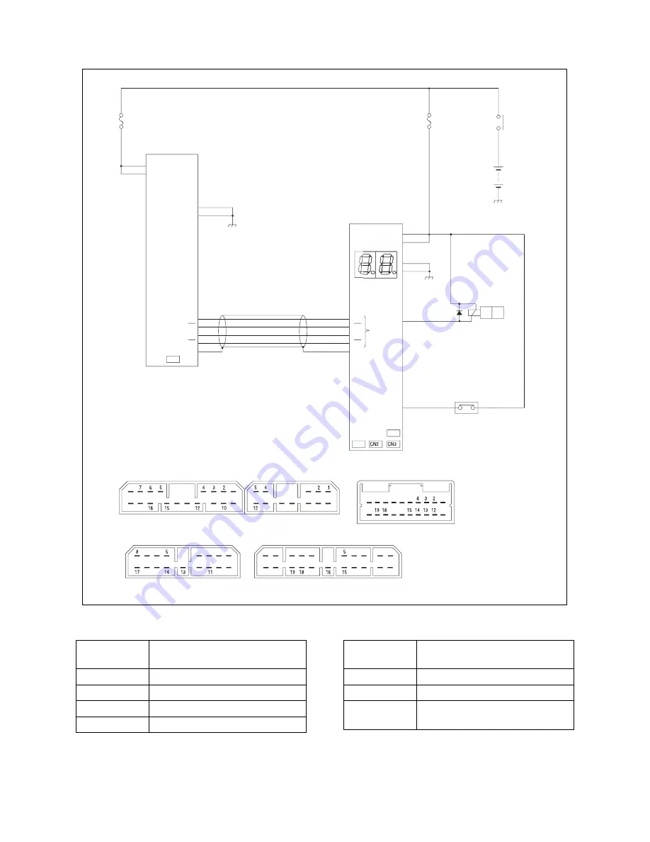
Figure 59
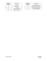
Reference
Number
Description
1
Battery
2
Battery Relay
3
Fuse
4
e-EPOS Controller
5
Instrument Panel
6
Solenoid Valve (Pressure Up)
7
Power Boost Switch (Top of
Right Work Lever)
Reference
Number
Description
Summary of Contents for Solar 470LC-V
Page 2: ......
Page 4: ......
Page 7: ...1SAFETY...
Page 8: ......
Page 46: ...S0102000 Page 38 Track Excavator Safety...
Page 47: ...1SPECIFICATIONS...
Page 48: ......
Page 54: ...S0202090K Page 6 Specifications for Solar 470LC V...
Page 70: ...S0202090K Page 22 Specifications for Solar 470LC V...
Page 71: ...1GENERAL MAINTENANCE...
Page 72: ......
Page 86: ...S0302000 Page 14 General Maintenance Procedures Return to Master Table of Contents...
Page 99: ...1UPPER STRUCTURE...
Page 100: ......
Page 102: ...S0402040K Page 2 Cab TABLE OF CONTENTS Removal 3 Installation 6...
Page 116: ...S0403050K Page 8 Counterweight Return to Master Table of Contents...
Page 140: ...S0407000 Page 6 Swing Bearing...
Page 155: ...S0408060 Page 15 Swing Reduction Gearbox...
Page 163: ...1LOWER STRUCTURE AND CHASSIS...
Page 164: ......
Page 190: ...S0505120 Page 26 Track Assembly Return to Master Table of Contents...
Page 191: ...1ENGINE AND DRIVE TRAIN...
Page 192: ......
Page 203: ...S0605060K Page 11 Air Conditioner Face and Defroster ARS1300L Figure 12...
Page 218: ...S0605060K Page 26 Air Conditioner...
Page 227: ...1HYDRAULICS...
Page 228: ......
Page 258: ...S0702190K Page 30 Hydraulic System Troubleshooting Testing and Adjustment...
Page 260: ...S0703010K Page 2 Accumulator TABLE OF CONTENTS General Description 3 Specifications 4...
Page 264: ...S0703010K Page 6 Accumulator...
Page 272: ...S0704090K Page 8 Center Joint Swivel...
Page 281: ...S0705000 Page 9 Cylinders...
Page 285: ...S0705000 Page 13 Cylinders...
Page 289: ...S0705000 Page 17 Cylinders...
Page 297: ...S0705000 Page 25 Cylinders...
Page 306: ...S0705000 Page 34 Cylinders 17 Force out pin bushing 1 from body of cylinder Figure 28...
Page 310: ...S0705000 Page 38 Cylinders...
Page 317: ...S0707260 Page 7 Swing Motor...
Page 321: ...S0707260 Page 11 Swing Motor SPECIAL TOOLS Figure 5...
Page 338: ...S0707260 Page 28 Swing Motor...
Page 350: ...S0707365 Page 12 Travel Motor With Gearbox A6V160HD PARTS LIST Travel Motor Figure 12 HTS6331...
Page 354: ...S0707365 Page 16 Travel Motor With Gearbox A6V160HD Travel Motor Control HTS6331 Figure 14...
Page 383: ...S0707365 Page 45 Travel Motor With Gearbox A6V160HD 29 Remove gasket Figure 91 Figure 91 3061...
Page 401: ...S0708325K Page 3 Main Pump Rexroth...
Page 402: ...S0708325K Page 4 Main Pump Rexroth SECTIONAL VIEW A8VO200LA1KH1 63 ASS0010L Figure 1...
Page 403: ...S0708325K Page 5 Main Pump Rexroth ASS0020L Figure 2...
Page 414: ...S0708325K Page 16 Main Pump Rexroth REMOVE THE CONTROL HOUSING ASS0280L Figure 29...
Page 450: ...S0708325K Page 52 Main Pump Rexroth INSTALLATION OF COVER AUXILIARY DRIVE ASS1100L Figure 111...
Page 454: ...S0708325K Page 56 Main Pump Rexroth...
Page 459: ...S0709402K Page 5 Control Valve Kayaba Model KVMG 400 DA...
Page 461: ...S0709402K Page 7 Control Valve Kayaba Model KVMG 400 DA Figure 1...
Page 463: ...S0709402K Page 9 Control Valve Kayaba Model KVMG 400 DA Figure 2...
Page 465: ...S0709402K Page 11 Control Valve Kayaba Model KVMG 400 DA Figure 3...
Page 475: ...S0709402K Page 21 Control Valve Kayaba Model KVMG 400 DA...
Page 477: ...S0709402K Page 23 Control Valve Kayaba Model KVMG 400 DA Figure 13...
Page 483: ...S0709402K Page 29 Control Valve Kayaba Model KVMG 400 DA PARTS LIST Figure 30...
Page 484: ...S0709402K Page 30 Control Valve Kayaba Model KVMG 400 DA Figure 31...
Page 485: ...S0709402K Page 31 Control Valve Kayaba Model KVMG 400 DA Figure 32...
Page 509: ...S0709402K Page 55 Control Valve Kayaba Model KVMG 400 DA Figure 57 S N 1051 and Up...
Page 512: ...S0709402K Page 58 Control Valve Kayaba Model KVMG 400 DA...
Page 560: ...S0792170K Page 4 Hydraulic Schematic S470LC V SOLAR 470LC V Figure 2...
Page 561: ...S0792170K Page 5 Hydraulic Schematic S470LC V...
Page 562: ...S0792170K Page 6 Hydraulic Schematic S470LC V...
Page 563: ...1ELECTRICAL SYSTEM...
Page 564: ......
Page 618: ...S0802220K Page 54 Electrical System...
Page 637: ...S0802220K Page 73 Electrical System...
Page 644: ...S0892170K Page 4 Electrical Schematic S470LC V SOLAR 470LC V Figure 2...
Page 646: ...S0892170K Page 6 Electrical Schematic S470LC V...
Page 647: ...1ATTACHMENTS...
Page 648: ......
Page 668: ......

