Chapter 12 Instructions on Loop Embroidery
128
BECS-D19 User’s Manual
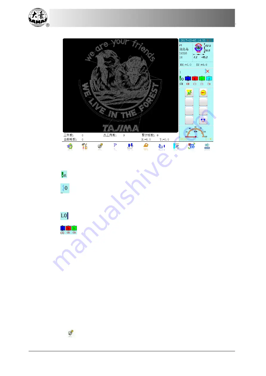
The above picture is the main interface after switch to loop embroidery head.
The above two main interfaces have the following differences:
(
1
)
indicates the shuttle position, a represents the curent position;
(
2
)
represents thread loosing position, 0 means thread tightening at down
position of shuttle, and as for the meaning of number, please see “thread loosing
position adjustment” of “manual adjustment”;
(
3
)
represents stitch type, L means looping, 0 indicates the needle height level;
(
4
)
is the color-changing order list, each group consisting of three items:
shuttle position: b; stitch type: C; needle height: 0.
12.3 Loop Embroidery Procedure
(
1
)
Input loop embroidery pattern: select, change and edit pattern according to need;
(
2
)
Modify parameters: select color-changing order, stitch type and needle height; in
case of manual color-changing, select shuttle position, stitch type (looping or chained)
and needle height manually;
(
3
)
Check loop embroidery head: to ensure normal work status;
(
4
)
Pull bar to embroider.
12.4 Parameters and Settings
Press
in the main interface and press the icons at the low-right corner to select


