
4.General Specifications
© 2023 China Daheng Group, Inc. Beijing Image Vision Technology Branch 22
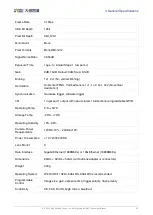
4.9.
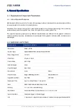
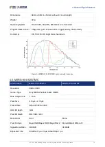
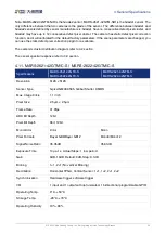
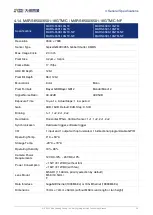
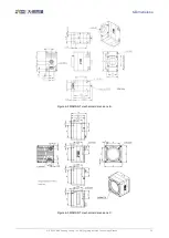
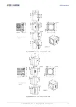
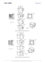
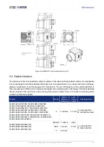
MARS-2621-42GTM/C \ MARS-2622-42GTM/C
Specifications
MARS-2621-42GTC
MARS-2622-42GTC
MARS-2621-42GTM
MARS-2622-42GTM
Resolution
5120 × 5120
Sensor Type
Gpixel GMAX0505, Global Shutter CMOS
Max. Image Circle
1.1 inch
Pixel Size
2.5μm × 2.5μm
Frame Rate
41.8fps
ADC Bit Depth
12bit
Pixel Bit Depth
8bit, 12bit
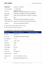
Mono/Color
Color
Mono
Pixel Formats
Bayer GB8/Bayer GB12
Mono8/Mono12
Signal Noise Ratio
35.24dB
35.54dB
Exposure Time
14μs~1s, Actual Steps: 1 row period
Gain
0dB~16dB. Default: 0dB, Step: 0.1dB
Binning
1×1, 2×1 (No vertical Binning)
Decimation
Horizontal FPGA, Vertical Sensor: 1×1, 1×2, 2×1, 2×2 (No vertical
decimation)
Synchronization
Hardware trigger, software trigger
I/O
1 input and 1 output with opto-isolated, 1 bidirectional programmable GPIO
Operating Temp.
0°C~+50°C
Storage Temp.
-20°C~+70°C
Operating Humidity
10%~80%
Camera Power
Requirements
12VDC-10% ~ 24VDC+10%
Power Consumption
< 12.7W @ 24VDC
Lens Mount
C


