8.Features
© 2023 China Daheng Group, Inc. Beijing Image Vision Technology Branch 59
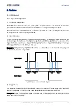
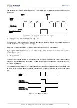
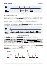
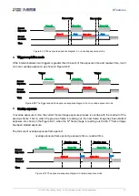
the exposure transmission. When the transfer is completed, the "AcquisitionTriggerWait" signal will be
pulled high.
Signal 2
Signal1
Image1
Tri gg er
Si gn al
Acq ui sition Tri gge rWa it
Si gn al
O utpu t Ima ge
Image2
Image4
Image3
Image5
Image6
Figure 8-8 "AcquisitionTriggerWait" signal schematic diagram
2)
Setting the user-defined status for the output lines
The MARS-GT series camera can select the user-defined output by setting "LineSource", by setting
"UserOutputValue" to configure the output signal.
By setting "UserOutputSelector" to select UserOutput0, UserOutput1 or UserOutput2.
By setting "UserOutputValue" to set the user-defined output value, and the default value is false when the
camera is powered on.
3)
Output Inverter
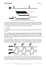
In order to facilitate the camera I/O configuration and connection, the MARS-GT series camera has the
function of configurable output signal level. The user can select whether the output level is reverse or not
by setting "LineInverter".
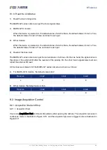
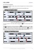
The default output signal level is false when the camera is powered on, indicating that the output line level
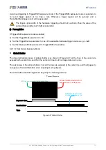
is not reversed. If it is set as true, indicating that the output line level is reversed. As shown in the Figure
8-9.
OutPut
Signal
Output Line
LineInv erter= False
Output Line
LineInv erter= True
Figure 8-9 Set output line reversion


