background image


8.Features


© China Daheng Group, Inc. Beijing Image Vision Technology Branch                                                              61 

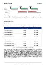
Time

Frame N

Frame N+1

Frame N+2

Frame N

Frame N+1

Sensor 
Exposure

Sensor 
Readout


Trigger

Trigger

Trigger

Figure 8-25 The trigger acquisition exposure sequence diagram in overlaping exposure mode 

Compared  with  non-overlaping  exposure  mode,  in  overlaping  exposure  mode,  the  camera  can  obtain 
higher frame rate. 

8.3. Basic Features 

8.3.1. Gain 

The MARS-G-P series camera can adjust the analog gain, and the range of analog gain is as follows: 

Model 

Adjustment Range 

Default/Steps 

MARS-880-13GM/C-P 

0-24dB 

0dB, 0.1dB 

MARS-1230-9GM/C-P 

0-23.9dB 

0dB, 0.1dB 

MARS-3140-3GM/C-P 

0-24dB 

0dB, 0.1dB 

MARS-880-13GM/C-P ETR 

0-24dB 

0dB, 0.1dB 

MARS-2621-4GM-P ETR 

0-16dB 

0dB, 0.1dB 

MARS-2622-4GM-P ETR 

0-16dB 

0dB, 0.1dB 

MARS-2621-4GM-P NIR ETR 

0-16dB 

0dB, 0.1dB 

MARS-2622-4GM-P NIR ETR 

0-16dB 

0dB, 0.1dB 

Table 8-4 MARS-G-P series camera analog gain adjustment range 

When the analog gain changes, the response curve of the camera changes, as shown in Figure 8-26. The 
horizontal axis represents the output signal of the sensor in the camera, and the vertical axis represents 
the  gray  value  of  the  output  image. When  the  amplitude  of  the  sensor  output  signal  remains  constant, 
increasing the gain makes the response curve steeper, and that makes the image brighter. For every 6dB 
increases of the gain, the gray value of the image will double. For example, when the camera has a gain 
of 0dB, the image gray value is 126, and if the gain is increased to 6dB, the image gray will increase to 
252. Thus, increasing gain can be used to increase image brightness. When the environment brightness 
and exposure time keep constant, another way to increase the image brightness is to change the camera's 
digital gain by modifying the lookup table. 

Summary of Contents for MARS GigE

Page 1: ...MARS GigE Cameras User Manual Version V1 1 0 Date 2022 06 28 China Daheng Group Inc Beijing Image Vision Technology Branch...

Page 2: ...Branch The right is also reserved to modify or change any parts of this manual in the future without prior notification All other trademarks are the properties of their respective owners 2022 China Da...

Page 3: ...extremely low noise The camera is equipped with standard GigE interface supports Power over Ethernet PoE IEEE802 3af compliant and is easy to install and use The MARS family cameras are especially su...

Page 4: ...2 Camera Power 6 3 3 Camera Driver Installation 7 3 3 1 System Requirements 7 3 3 2 Driver Installation 7 3 4 Camera IP Configuration 8 3 5 Open Device and Start Acquisition 8 4 General Specification...

Page 5: ...2 6 2 7 HN P 25M Series 32 7 Electrical Interface 34 7 1 LED Light 34 7 2 Ethernet Port 34 7 3 I O Port 34 7 3 1 Line0 Opto isolated Input Circuit 35 7 3 2 Line1 Opto isolated Output Circuit 38 7 3 3...

Page 6: ...ite Balance Adjustment 69 8 3 6 Test Pattern 70 8 3 7 User Set Control 71 8 3 8 Device User ID 74 8 3 9 Timestamp 74 8 3 10 Binning 75 8 3 11 Decimation 77 8 3 12 Reverse X and Reverse Y 79 8 3 13 Dig...

Page 7: ...2 User Guide 104 9 1 2 1 Refresh Devices 104 9 1 2 2 Auto Config 105 9 1 2 3 Display Information 106 9 1 2 4 Configure IP Address 106 9 1 2 5 IP Configuration Mode 107 9 1 2 6 Change the Device User I...

Page 8: ...ile Save FFC Data to File 122 9 3 3 Precautions 122 9 3 3 1 FFC is not Supported 122 9 3 3 2 Preview 123 9 4 Frame Rate Calculation Tool 123 9 5 Static Defect Correction Plugin 125 9 5 1 GUI 125 9 5 2...

Page 9: ...rers The MARS G P series digital camera transmits image data through the GigE data interface Thanks to the locking screw connectors the MARS series cameras can secure the reliability of cameras deploy...

Page 10: ...ical Drawing and Software Downloads Product related document CAD Technical drawing and software can be downloaded from the Downloads of DAHENG IMAGING website The relevant contents are as follows Docu...

Page 11: ...metal to discharge the electro static before operating cameras 2 2 Environmental Requirements 1 Housing temperature during operation 0 C 45 C humidity during operation 10 80 Storage temperature 20 C 7...

Page 12: ...ion Technology Branch 4 2014 30 EU Electromagnetic Compatibility Restriction 2011 65 EU Restriction of Hazardous Substances RoHS and its revised directive 2015 863 EU Operation of this equipment in a...

Page 13: ...o develop their own control programs 6 Programmer s Manual This manual is the users programming guide that instructs the users how to configure the programming environment and how to control cameras a...

Page 14: ...rogramming interface API no matter what interface technology is being used It mainly includes the following modules GenAPI an XML description file format defining how to capture the features of a devi...

Page 15: ...as in the MARS series The GalaxySDK contains various operating systems such as windows and Linux The requirements for the operating system and version of the installation package are as follows Operat...

Page 16: ...ls on how to use the tool please refer to section 9 1 1 Connect the GigE camera to the network port of the current host 2 Open the GigE IP Configurator of the installation package 3 Click Auto Config...

Page 17: ...hnology Branch 9 1 Click the icon on the Toolbar in the GalaxyView to refresh device list 2 After the device is enumerated double click the device enumerated in the device list 3 Click the icon on the...

Page 18: ...spectral response graphs given by different manufacturers are different Some graphs ordinate is relative sensitivity response and abscissa is wavelength Some graphs ordinate is QE and abscissa is wave...

Page 19: ...PoE Power over Ethernet IEEE802 3af compliant or 12VDC 10 24VDC 10 supplied via the camera s 12 pin Hirose connector Power Consumption 3W 12VDC 3 5W PoE Lens Mount C Dimensions 50 4mm 62mm 62mm withou...

Page 20: ...Specifications China Daheng Group Inc Beijing Image Vision Technology Branch 12 4 2 2 Spectral Response Figure 4 1 MARS 880 13GC P sensor spectral response Figure 4 2 MARS 880 13GM P sensor spectral...

Page 21: ...Bit Depth 12bit Pixel Bit Depth 8bit 12bit Shutter Time 36 s 1s Gain 0dB 23 9dB Pixel Formats Bayer RG8 Bayer RG12 Mono8 Mono12 Signal Noise Ratio 39 88dB 39 75dB Synchronization Hardware trigger sof...

Page 22: ...64bit OS Data Interface Fast Ethernet 100Mbit s or Gigabit Ethernet 1000Mbit s Programmable Control Image size gain exposure time trigger polarity flash polarity Conformity CE RoHS GigE Vision GenICam...

Page 23: ...s 1s Gain 0dB 24dB Pixel Formats Bayer RG8 Bayer RG12 Mono8 Mono12 Signal Noise Ratio 39 83dB 39 77dB Synchronization Hardware trigger software trigger I O 1 input and 1 output with opto isolated 2 p...

Page 24: ...64bit OS Data Interface Fast Ethernet 100Mbit s or Gigabit Ethernet 1000Mbit s Programmable Control Image size gain exposure time trigger polarity flash polarity Conformity CE RoHS GigE Vision GenICam...

Page 25: ...to 7 ADC Bit Depth 12bit Pixel Bit Depth 8bit 12bit Shutter Time 36 s 1s Gain 0dB 24dB Pixel Formats Bayer RG8 Bayer RG12 Mono8 Mono12 Signal Noise Ratio 39 89dB 39 81dB Synchronization Hardware trig...

Page 26: ...t OS Data Interface Fast Ethernet 100Mbit s or Gigabit Ethernet 1000Mbit s Programmable Control Image size gain exposure time trigger polarity flash polarity Conformity CE RoHS GigE Vision GenICam IEE...

Page 27: ...erved bandwidth to 5 ADC Bit Depth 12bit Pixel Bit Depth 8bit 12bit Shutter Time 14 s 1s Gain 0dB 16dB Pixel Formats Mono8 Mono12 Signal Noise Ratio 35 93dB Synchronization Hardware trigger software t...

Page 28: ...ive defect pixel cluster while Grade2 chips may have up to 12 consecutive defect pixel cluster It also comes out with Static Defect Correction function The default factory parameters will be calibrate...

Page 29: ...and reserved bandwidth to 5 ADC Bit Depth 12bit Pixel Bit Depth 8bit 12bit Shutter Time 14 s 1s Gain 0dB 16dB Pixel Formats Mono8 Mono12 Signal Noise Ratio 35 93dB Synchronization Hardware trigger so...

Page 30: ...ect pixel cluster while Grade2 chips may have up to 12 consecutive defect pixel cluster It also comes out with Static Defect Correction function The default factory parameters will be calibrated at th...

Page 31: ...a Daheng Group Inc Beijing Image Vision Technology Branch 23 5 Dimensions 5 1 Camera Dimensions Figure 5 1 MARS G P mechanical dimensions except MARS 3140 3GM C P Figure 5 2 MARS 3140 3GM C P M03 mech...

Page 32: ...0 3GM C P cameras are equipped with the standard M42 Mount M03 and the F Mount M02 lens adapters The back flange distance of the M42 Mount M03 lens is 12 mm in the air and the back flange distance of...

Page 33: ...stomizing the tripod adapter you need to consider the relationship between tripod adapter screw length and step thickness of tripod adapter 1 Screw length tripod adapter step thickness spring washer t...

Page 34: ...thickness from the table below Screw specification Tripod adapter step thickness mm Spring washer thickness mm Screwing length of camera screw thread mm M4 8 screw 2 2 1 4 8 M4 10 screw 4 2 1 4 8 If t...

Page 35: ...quency is 700nm which reduces the influence of invisible light on the image The monochrome models are equipped with transparent glasses Remove IR filters or transparent glasses will defocus the image...

Page 36: ...mum sensor size that the lens image can cover There are mainly 1 2 2 3 1 1 2 1 1 1 4 3 and so on When selecting a lens make sure that the max image circle of the lens is not smaller than the sensor si...

Page 37: ...mechanical structure the optical axis fluctuates below 10 m The housing is small and compact the minimum outer diameter is only 29 5mm and it can be installed in various limited spaces Easy to install...

Page 38: ...HN 2516 5M C2 3X HN 3519 5M C2 3X HN 5024 5M C2 3X 6 2 3 HN 6M Series The HN 6M series lenses are 6 megapixels lenses for industrial suitable for sensors with max image circle of 2 3 This series of l...

Page 39: ...tent from the center to the periphery greatly improving the distance between iris and photography Models HN 0826 20M C1 1X HN 1226 20M C1 1X HN 1624 20M C1 1X HN 2520 20M C1 1X HN 3522 20M C1 1X HN 50...

Page 40: ...mpact the minimum outer diameter is only 32 0mm and it can be installed in various limited spaces Ultra low optical distortion Models HN P 0824 10M C2 3 HN P 1220 10M C2 3 HN P 1618 10M C2 3 HN P 2518...

Page 41: ...6 Filters and Lenses China Daheng Group Inc Beijing Image Vision Technology Branch 33 HN P 3524 25M C1 2 1 HN P 5024 25M C1 2 1...

Page 42: ...arted in the userset mode the parameter set is wrong and the camera is switched to the default mode to start Use the IP Configurator to save the camera IP or re save the userset After the camera is po...

Page 43: ...d 10 GND White Purple PWR GND GPIO GND 11 NC2 White Orange Not Connected reserved 12 NC3 White Pink Not Connected reserved Table 7 2 I O port definition back sight of camera The input power of MARS G...

Page 44: ...a circuit limiting resistance is needed in the external input The recommended resistance is shown in Table 7 3 External input voltage Circuit limiting resistance Rlimit Line0 input voltage 5V Non or 9...

Page 45: ...ge have influence on delay time of opto isolated input circuit Delay time in typical application environment temperature is 25 C is as shown in Table 7 4 Parameter Test condition Value s Rising edge d...

Page 46: ...utput voltage V Output current mA 5V 1k 0 90 4 16 12V 1k 0 97 11 11 24V 1k 1 04 23 08 Table 7 5 Output voltage and output current of opto isolated output circuit in typical application environment Ris...

Page 47: ...s to 90 of amplitude Falling time tf the response time for LINE1 to decrease from 90 of the amplitude to 10 Storage time ts the response time from OUTPUT1 decreases to 50 of amplitude to LINE1 rises t...

Page 48: ...2 3 voltage Logic 1 input voltage 1 9V 24V Line2 3 voltage The status is unstable when input voltage is between 0 6V and 1 9V which should be avoided When input of Line2 3 is high input current is low...

Page 49: ...er description as shown in Figure 7 4 7 3 3 2 Line2 3 is Configured as Output Range of external voltage EXVCC is 5 24V Maximum output current of Line2 3 is 25mA output impedance is 40 Output voltage a...

Page 50: ...me tf 1 82 1 94 Rising time delay tr td 0 19 0 26 Falling time delay tf ts 1 97 2 09 Table 7 8 Delay time when GPIO is configured as output in typical conditions When Line2 3 is configured as output t...

Page 51: ...ering feature including rising edge filtering and falling edge filtering The user can set the trigger filter feature by setting the TriggerFilterRaisingEdge and the TriggerFilterFallingEdge The range...

Page 52: ...etting input line reverse 8 1 2 Output Mode Operation 1 Configuring Line as output The MARS G P series camera has three output signals Line1 Line2 and Line3 In which the Line1 is a uni directional opt...

Page 53: ...nt light source or the alarm light two level types are available high level or low level For example select line2 as the output line the output source is selected as UserOutput1 and the output value i...

Page 54: ...d to avoid excessive triggering It is recommended to use the TriggerWait signal only when the camera is configured for hardware trigger For software trigger please use the AcquisitionStatus When the c...

Page 55: ...e MARS G P series camera can select the user defined output by setting LineSource by setting UserOutputValue to configure the output signal By setting UserOutputSelector to select UserOutput0 UserOutp...

Page 56: ...nes level status bit of the MARS G P series camera are shown in Table 8 1 The default polarity does not reverse and the default value is 0xC Line3 Line2 Line1 Line0 1 1 0 0 Table 8 1 Camera line statu...

Page 57: ...uisition Stop It can send AcquisitionStop command to camera at any time The acquisition stop process is irrelevant to acquisition mode But different stop time will result in different process as shown...

Page 58: ...igger type is arbitrary After executing the AcquisitionStart command the camera waits for a trigger signal which may be a software trigger or a hardware trigger of the camera When the camera receives...

Page 59: ...the trigger mode is set to Off After executing the AcquisitionStart command the camera will continuously acquire images until it receives the AcquisitionStop command You can check if the camera is in...

Page 60: ...quired until the value of the Acquisition burst frame count parameter is reached For example the FrameStart trigger mode and the FrameBurstStart trigger mode are selected at the same time If the Acqui...

Page 61: ...trigger mode to continuous mode at point 4 and then the camera works in continuous mode Switch trigger mode during blanking or exposure Acquisition Mode Camera output Continuous mode Continuous Frame...

Page 62: ...ON 2 Set the Trigger Source to Software 3 Send Software Trigger command All the software trigger commands are sent by the host through the Gigabit Ethernet bus to trigger the camera to capture and tr...

Page 63: ...time is zero The features like trigger polarity trigger delay and trigger filter can be select in the GalaxyView The camera s trigger source Line0 use opto isolated circuit to isolate signal Its inter...

Page 64: ...e start Image readout Figure 8 19 Exposure delay The following table shows the total exposure delay time for each sensor T1 is calculated according to the typical delay 5 s of line0 If it is line2 3 T...

Page 65: ...are exposed at the same time and the images do not appear offset and distortion when capturing moving objects The time width of the flash signal can be got by the following formula T T Exposure time R...

Page 66: ...RS 880 13GM C P Global Shutter 36 1000000 1 1 row period MARS 1230 9GM C P Global Shutter 36 1000000 1 1 row period MARS 3140 3GM C P Global Shutter 63 1000000 1 1 row period MARS 880 13GM C P ETR Glo...

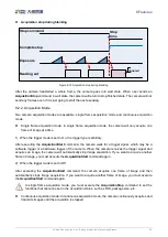
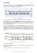
Page 67: ...overlaping exposure The user cannot assign the overlaping exposure or non overlaping exposure directly it depends on the frequency of trigger signal and the exposure time The two exposure mode are de...

Page 68: ...8 24 when the Nth frame image is reading out the N 1th frame image has been started exposure The formula of overlaping exposure frame period overlaping exposure frame period exposure time readout tim...

Page 69: ...P NIR ETR 0 16dB 0dB 0 1dB MARS 2622 4GM P NIR ETR 0 16dB 0dB 0 1dB Table 8 4 MARS G P series camera analog gain adjustment range When the analog gain changes the response curve of the camera changes...

Page 70: ...he pixel format supported by the camera Model Pixel Format MARS 880 13GM C P Mono8 Mono12 BayerRG8 BayerRG12 MARS 1230 9GM C P Mono8 Mono12 BayerRG8 BayerRG12 MARS 3140 3GM C P Mono8 Mono12 BayerRG8 B...

Page 71: ...mat is set to mono10 or Mono12 each pixel is 16 bits When Mono10 is selected the effective data is only 10 bits the six unused most significant bits are filled with zero When Mono12 is selected the ef...

Page 72: ...w pixel values are arranged G10 is the first pixel value of the second row for the green component the B11 is the second pixel value for the blue component and so on and the second row of pixel values...

Page 73: ...the second pixel value for the green component and so on and the second row of pixel values are arranged BayerGR10 BayerGR12 When the pixel format is set to BayerGR10 or BayerGR12 the value of each pi...

Page 74: ...Raw 8 9 10 11 12 12 13 14 15 16 17 18 19 20 21 22 Height OffsetY OffsetX Width ROI Column When reducing the height of the ROI the maximum frame rate of the camera will be raised Please refer to sectio...

Page 75: ...t image width is 1024 the height is 1000 and then the ROI setting is AAROIOffsetX 100 AAROIOffsetY 50 AAROIWidth 640 AAROIHeight 480 The relative position of the ROI and the image is shown in Figure 8...

Page 76: ...is kept near to the expected gray level The expected gray value is set by the user and it is related to the data bit depth For 8bit pixel data the expected gray value range is 0 255 and for 12bit pix...

Page 77: ...480 The relative position of the ROI and the image is shown in Figure 8 28 ROI 1024 1000 ROI 640 480 100 50 Figure 8 28 An example for the relative position between the ROI and the current image 8 3 5...

Page 78: ...ame increases by 1 compared to the previous frame until to 255 and then the next frame gray value returns to 0 and so on A printscreen of a single frame is shown in Figure 8 29 Figure 8 29 Gray gradie...

Page 79: ...e in the same position remains unchanged A printscreen of the static diagonal gray gradient test image is shown in Figure 8 31 Figure 8 31 Static diagonal gray gradient test image 8 3 7 User Set Contr...

Page 80: ...efault configuration parameters Default Before the camera leaves the factory the camera manufacturer will test the camera to assess the camera s performance and optimize the configuration parameters o...

Page 81: ...io R G B LUT Load parameters UserSetLoad Load the vendor default configuration parameters or the user configuration parameters into the effective configuration parameters After this operation is perfo...

Page 82: ...estamp The timestamp feature counts the number of ticks generated by the camera s internal device clock As soon as the camera is powered on it starts generating and counting clock ticks The counter is...

Page 83: ...xel values of adjacent pixels of the same color R G B G R G G B Figure 8 33 Horizontal color Binning by 2 R G B G R G G B Figure 8 34 Vertical color Binning by 2 When the horizontal Binning factor and...

Page 84: ...without affecting the camera s response to light Considerations When Using Binning 1 Effect on ROI settings When Binning is used the value of the current ROI of the image the maximum ROI of the image...

Page 85: ...ecify a vertical Decimation factor of n the camera transmits only every nth pair of rows For example when you specify a vertical Decimation factor of 2 the camera skips rows 1 and 2 transmits rows 3 a...

Page 86: ...cimation Considerations When Using Decimation 1 Effect on ROI settings When you are using Decimation the settings for your image ROI refer to the resulting number of rows and columns Taking MARS 3140...

Page 87: ...e X and Reverse Y The Reverse X and Reverse Y features can mirror acquired images horizontally vertically or both Enabling Reverse X To enable Reverse X set the ReverseX parameter to true The camera m...

Page 88: ...st bear in mind that the position of the ROI relative to the sensor remains the same Therefore the camera acquires different portions of the image depending on whether the Reverse X or the Reverse Y f...

Page 89: ...set to the maximum value Configuring Digital Shift To configure the digital shift factor enter the expected value for the DigitalShift parameter By default the parameter is set to 0 i e digital shift...

Page 90: ...The Acquisition Status feature can determine whether the camera is waiting for trigger signals This is useful if you want to optimize triggered image acquisition and avoid over triggering To determine...

Page 91: ...mera black level adjustment range 8 3 16 Remove Parameter Limits The range of camera parameters is usually limited and these factory limits are designed to ensure the best camera performance and high...

Page 92: ...14 1000000 14 15000000 Auto Exposure 14 1000000 14 15000000 Gain 0 16 0 24 Auto Gain 0 16 0 24 Black Level 0 1023 0 1023 Sharpness 0 3 0 63 White Balance component factor 0 15 998 0 31 998 Auto White...

Page 93: ...nly ExposureEnd signal is supported The Timer can configure a timer output signal that goes high on a specific event or signal and goes low after a specific duration And the timer is cleared when the...

Page 94: ...them Off means no reset SoftWare means software reset Line0 Line2 or Line3 means reset through IO interface input signal The polarity of the reset signal only supports RisingEdge which means reset the...

Page 95: ...ined mode User RGBtoRGB Default color transformation parameters provided to the camera when it leaves the factory User a Set the ColorTransformationValueSelector parameter to the expected position in...

Page 96: ...ion 8 4 2 Gamma The Gamma can optimize the brightness of acquired images for display on a monitor 1 Prerequisites If the GammaEnable parameter is available it must be set to true 2 How it works The ca...

Page 97: ...of image information If the Gamma feature is required and no image information is lost avoid using the Gamma feature in 10 bit or 12 bit pixel format 4 Additional parameters Depending on your camera...

Page 98: ...basically an indexed list of numbers b In the lookup table you can define replacement values for individual pixel values For example you can replace a gray value of 0 minimum gray value by a gray valu...

Page 99: ...teps 1 and 2 for all pixel values that need to be changed to set the parameters to the target pixel values in turn e Set the LutEnable parameter to true means that the lookup table feature is enabled...

Page 100: ...obtain save and preview the Flat Field Correction factor The plugin interface is shown in Figure 8 58 Figure 8 58 Flat Field Correction Plugin interface There are three ways to obtain the Flat Field...

Page 101: ...orrection Plugin the process of obtaining FFC factor is shown in the figure below where the yellow parts are optional steps For detailed introduction of Flat Field Correction Plugin please see section...

Page 102: ...e of the darkest area of the brightfield is recommended to be greater than 20 It is recommended to control the brightfield gray value by adjusting the exposure time or light source and do not adjust t...

Page 103: ...cal defects of the image sensor the camera has defect pixels Some of these defect pixels are fixed at the same gray value and do not change with the scene which are called dead pixels In acquired imag...

Page 104: ...aximum allowable frame rate of the network is 9fps and the MARS 1230 9GM C P camera meets the front end sensor s maximum acquisition frame rate of 9fps In addition to the limitations of network bandwi...

Page 105: ...frame rate is 5fps In conclusion the frame rate of the camera takes the minimum of the maximum allowable frame rate of the network the acquisition frame rate and the exposure frame rate 8 5 2 Stream C...

Page 106: ...is calculated as follows The time required to transmit a single stream packet T 8 The time of packet delay is 125 000 000 Among them the is packet size is packet delay BandW is reserved bandwidth is...

Page 107: ...use frame transfer delay to avoid this problem In trigger mode by setting the Transfer Control Mode as User Controlled when the camera receives software trigger command or hardware trigger signal and...

Page 108: ...the port value of the event channel is set to 0 the camera will not send the event to the host In other cases the camera needs to receive a host reply packet before sending the next event When the eve...

Page 109: ...ger Event When the camera receives the FrameTrigger hardware trigger signal or software trigger signal if the front end sensor is exposing it will not be able to respond to the new FrameTrigger signal...

Page 110: ...if it does not receive the FrameTrigger signal the camera will send a FrameStartWait event to the host 8 6 8 FrameBurstStartWait Event When the camera is in the AcquisitionTrigger mode the camera sta...

Page 111: ...ol can reset device and reconnect device a Reset device The effect is the same as powering Off On The program inside the device is reloaded b Reconnect device The effect is the same as closing device...

Page 112: ...ranges from 169 254 0 1 to 169 254 255 254 Device User ID The user defined identity for camera settings and the content is a character string Save Select the Save button the tool will save the curren...

Page 113: ...ame subnet IP is invalid and IP conflicts with other devices the program will modify the device s IP to the same subnet After selecting the Auto Config 2 According to device s IP address If the curren...

Page 114: ...camera feature in the tree list the following camera information is displayed in the information display window below the left side of the main window Vendor The name of the camera vendor Model The n...

Page 115: ...e tool select the camera whose IP configuration you want to change b In the right pane of the tool select DHCP c Select the Save button When the tool has finished saving the information in the top pan...

Page 116: ...ce does not support this feature Reset Device When the device is not convenient to power down but also need to reload the program this feature can be used at this time Reconnect Device This function i...

Page 117: ...eras IP address are the same If the cameras IP address are the same a red exclamation mark will be displayed in the right of the camera list as shown in the Figure 9 5 2 The camera s IP address and th...

Page 118: ...ew exe After opening the device that you want to operate through this software you can open LUT Create Tool from the menu bar plugin list With the plugin you can achieve the following functions 1 Adju...

Page 119: ...on again you need to select Write to Device The Lut parameter will be written to the UserSet0 After the device is powered on again select the Read From Device in the GroupBox to load the UserSet0 and...

Page 120: ...from device the tool will automatically load UserSet0 and then load the Lut saved by the device If the device supports LUTEnable it will automatically set LUTEnable to true to display the image effect...

Page 121: ...Device the polyline graph and image effects are updated to the lookup table in the device 3 While Read From Device is selected the polyline graph and image effects of the MERCURY2 and MARS 3140 3GM C...

Page 122: ...or default Lut and auto create Lut the widget interface will update the parameters stored when saving Lut the updated parameter values include Lut range Gamma brightness contrast and the values selec...

Page 123: ...ng will result in failure to read the file 5 Default The default option is the Lut data when the device is shipped from the factory and is the initial value in each situation If there is an error in o...

Page 124: ...RS 880 13GM C P ETR cameras will not save or restore the parameter while written to the device but the MERCURY2 GigE family MARS 3140 3GM C P MARS 2621 4GM P ETR MARS 2621 4GM P NIR ETR MARS 2622 4GM...

Page 125: ...reading writing Lut and Auto Creat Lut you need to rely on some files in the installation package directory so do not arbitrarily change the installation package directory structure to avoid read wri...

Page 126: ...ightfield images Necessary operation 4 Execute FFC Calculate the flat field correction coefficient and Immediate effect 5 Preview Check the effects before and after the flat field correction Enable or...

Page 127: ...images For details on acquiring brightfield images please see section 8 4 5 1 Step 5 Select Execute FFC to complete the correction Step 6 You can check the effects before and after the flat field corr...

Page 128: ...if the black level is not the default value the prompt information given in the prompt box is as shown in Figure 9 14 That is when the flat field correction is executed the darkfield image is not use...

Page 129: ...Images the GalaxyView acquisition GUI will flash indicating that the device is acquiring the brightfield image and after the acquisition of brightfield images is completed the device Recovery the acq...

Page 130: ...lat field correction needs to be done again 3 When the flat field correction is completed the preview widget takes effect and the preview function can be used to check the effects before and after the...

Page 131: ...on Technology Branch 123 Figure 9 18 The camera does not support FFC 9 3 3 2 Preview The preview widget is grayed out when acquiring darkfield brightfield images and cannot be previewed 9 4 Frame Rate...

Page 132: ...vSCPDMaxValue represents maximum packet delay can be set under the current parameters 8 The BandwidthReserve represents the percentage of network bandwidth reserved for other network transmission whic...

Page 133: ...FPS approach 8fps After several attempts it can be concluded that when GevSCPD is set to 1100 the calculated result FPS is 8 00 fps 9 5 Static Defect Correction Plugin Static Defect Correction plugin...

Page 134: ...f Static Defect Correction Plugin Image Click Catch to acquire an image it will be displayed in the middle of the popup for further analysis Defect Pixel Analysis Users can decide the range of defect...

Page 135: ...be displayed in the GalaxyView acquisition GUI 2 When AcquisitionStart is selected click Catch button image acquisition will be finished directly 3 Uniform gray scale are required for counting defect...

Page 136: ...mera and 6 pixels from the boundary for color camera 9 5 2 4 How to use Defect Data File 1 The suffix of the defect data file is dp and the default save path is under the installation package director...

Page 137: ...gabit Network card 3 Contact with the technical support 4 Lose frames seriously in a multiple cameras application 1 Adjust the packet size or packet delay but frame rate reducing followed 2 Using mult...

Page 138: ...e of image acquisition If the size of the data block is reduced for example 120M memory is needed and the size of the data block is set to 10M then as long as the system has 12 consecutive memory size...

Page 139: ...features to 300000000us after Remove Parameter Limits 2020 09 21 8 V1 0 7 1 Add MARS 880 13GM C P ETR 2020 12 07 9 V1 0 8 1 Modify the mechanical dimensions of Figure 5 2 and Figure 5 3 2021 03 03 10...

Page 140: ...ou need to order products or inquire product information please contact our sales Tel 86 10 8282 8878 Email isupport daheng imaging com 12 2 Contact Support If you have any questions in using DAHENG I...

Reviews: