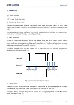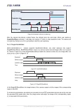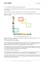
7.Electrical Interface
© China Daheng Group, Inc. Beijing Image Vision Technology Branch 92
7
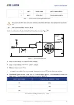
Line1-
White Green
Opto-isolated output -
8
Line1+
White Blue
Opto-isolated
Table 7-2 I/O port definition (back sight of the camera)
The polarity of GPIO pins cannot be reversed, otherwise, camera or other peripherals could burn
out.
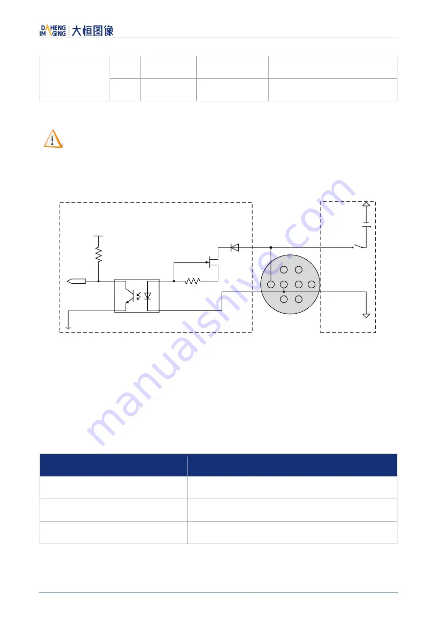
7.3.1. Line0 (Opto-isolated Input) Circuit
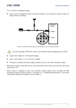
Hardware schematics of opto-isolated input circuit is shown as Figure 7-1.
8
5
1
4
3
7
2
6
3.3V
Line0+
Line0-
INPUT0
External
Circuit
5V-24V
Figure 7-1 Opto-isolated input circuit
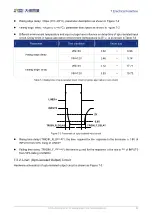
Logic 0 input voltage: 0V~+2.5V (Line0+ voltage)
Logic 1 input voltage: +5V~+24V (Line0+ voltage)
Minimum input current: 7mA
The status is unstable when input voltage is between 2.5V and 5V, which should be avoided
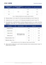
When peak voltage of input signal over 9V, a current limiting resistor is recommended to protect the
input Line0+. The recommended resistance is shown in Table 7-3
Line0+ input voltage
Circuit-limiting resistance Rlimit
9V
680Ω
12V
1kΩ
24V
2kΩ
Table 7-3 Circuit-limiting resistor value for Line0+

