7.Electrical Interface
© China Daheng Group, Inc. Beijing Image Vision Technology Branch 95
t
d
t
s
t
f
t
r
90%
10%
OUTPUT1
LINE1+
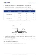
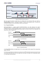
Figure 7-4 Parameter of opto-isolated output circuit
Delay time (td): the time required from 50% rising of OUTPUT1 to the decrease to 90% of the
maximum value of LINE1+
Falling time (tf): the time taken for the amplitude of LINE1+ to decrease from 90% to 10% of the
maximum value
Storage time (ts): the time required from 50% falling of OUTPUT1 to the rise to 10% of the maximum
value of LINE1+
Rising time (tr): the time for the response of LINE1+ to rise from 10% to 90% of its final value
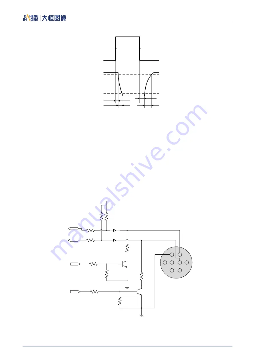
7.3.3. Line 2/Line3 (Bidirectional) Circuit
1
2
8
7
6
4
5
3
3.3V
Line2
Line3
INPUT2
INPUT3
OUTPUT2
OUTPUT3
PTC
PTC
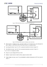
Figure 7-5 Line2/Line3 (bidirectional) circuit

