background image


8.Features


© China Daheng Group, Inc. Beijing Image Vision Technology Branch                                                              113 


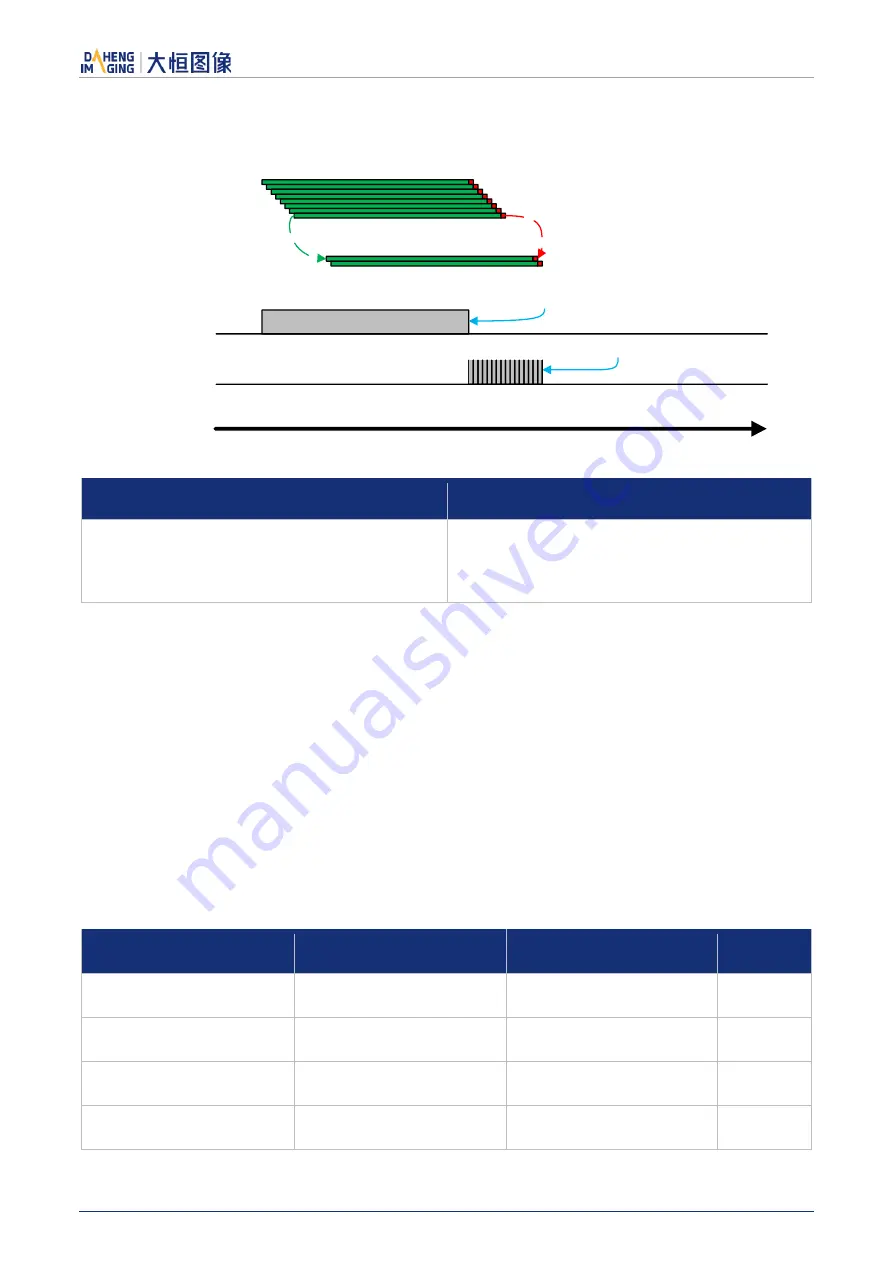
Electronic Rolling Shutter 

Exposure time

Readout time

Exposure line by line

Readout after exposure

Reading

Time

Exposing


Figure 8-15 Electronic rolling shutter 

Model 

Sensor Type 

MER-500-14U3M/C(-L)/MER-1070-14U3M/C(-L)/ 
MER-1520-13U3C(-L)/MER-1810-21U3C(-L)/ 
MER-630-60U3M/C(-L)/MER-2000-19U3M/C(-L)/ 
MER-1220-32U3M/C(-L) 

Electronic rolling shutter 

Table 8-4 Electronic rolling shutter camera models 

The  implementation  process  of  electronic  rolling  shutter  is  as  shown  in  Figure  8-15,  different  from  the 
global shutter, electronic rolling shutter exposures from the first line, and starts the second line exposure 
after a row period. And so on, after N-1 line, the N line starts exposing. When the first line exposure ends, 
it begins to read out the data, and it need a row period time to read out one line (including the line blanking 
time). When the first line reads out completely, the second line just begins to read out, and so on, when 
the N-1

th

 line is read out, the N

th

 line begins to read out, until the whole image is read out completely.   

The electronic  rolling shutter  has  low price and high resolution, which is a good choice for some  static 
image acquisition. 


Setting the exposure time 

The MER-U3 

series camera supports setting the exposure time, step: 1μs. The exposure time is shown 

as follows: 

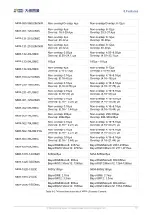
Model 

Exposure Mode 

Exposure Time Range(μs) 

Steps(μs) 

MER-031-860U3M/C(-L) 

Global Shutter 

20-1000000 

MER-031-860U3M(-L) NIR 

Global Shutter 

20-1000000 

MER-041-436U3M/C(-L) 

Global Shutter 

20-1000000 

MER-050-560U3M/C(-L) 

Global Shutter 

20-1000000 

Summary of Contents for MERCURY USB3

Page 1: ...MERCURY USB3 Vision Cameras User Manual Version V1 0 54 Date 2020 03 09 China Daheng Group Inc Beijing Image Vision Technology Branch...

Page 2: ...anch The right is also reserved to modify or change any parts of this manual in the future without prior notification All other trademarks are the properties of their respective owners 2020 China Dahe...

Page 3: ...h standard USB3 0 interface is easy to install and use The MERCURY family cameras are especially suitable for machine vision applications such as industrial inspection medical scientific research educ...

Page 4: ...nterface 4 3 2 Camera Power 5 3 3 Camera Driver Installation 6 3 3 1 System Requirements 6 3 3 2 Driver Installation 6 3 4 Open Device and Start Acquisition 6 4 General Specification 7 4 1 Explanation...

Page 5: ...4 12 2 Spectral Response 36 4 13 MER 160 227U3M C L 36 4 13 1 Parameter 36 4 13 2 Spectral Response 39 4 14 MER 230 168U3M C L 39 4 14 1 Parameter 39 4 14 2 Spectral Response 42 4 15 MER 231 41U3M C...

Page 6: ...ter 78 4 26 2 Spectral Response 80 4 27 MER 2000 19U3M C L 80 4 27 1 Parameter 80 4 27 2 Spectral Response 83 5 Dimensions 84 5 1 Camera Dimensions 84 5 2 Optical Interface 85 5 3 Tripod Adapter Dimen...

Page 7: ...Configuration 110 8 2 7 Set Exposure 112 8 2 8 Overlapping Exposure and Non overlapping Exposure 115 8 2 9 Strobe 117 8 3 Basic Features 119 8 3 1 Gain 119 8 3 2 Pixel Format 121 8 3 3 ROI 124 8 3 4 A...

Page 8: ...V 8 5 2 USB Interface Bandwidth 144 8 5 3 DeviceLinkThroughputLimit 144 8 5 4 Camera Acquisition Time 147 9 Software Tool 153 9 1 Frame Rate Calculation Tool 153 10 FAQ 155 11 Revision History 157 12...

Page 9: ...nd CMOS sensors from leading chip manufacturers The MER U3 and MER U3 L series digital cameras transmit image data through the USB3 0 data interface Thanks to the locking screw connectors the MERCURY...

Page 10: ...nt CAD Technical Drawing and Software Downloads Product related document CAD Technical drawing and software can be downloaded from the Downloads of DAHENG IMAGING website The relevant contents are as...

Page 11: ...ectro static discharge may damage cameras permanently so use suitable clothing cotton and shoes and touch the metal to discharge the electro static before operating cameras 2 2 Environmental Requireme...

Page 12: ...refer to the samples to develop their own control programs 5 Programmer s Manual This manual is the users programming guide that instructs the users how to configure the programming environment and ho...

Page 13: ...CON Note GEN i CAM standard GEN i CAM is administered by the European Machine Vision Association EMVA GenICam provides a generic programming interface for all kinds of cameras and devices It provides...

Page 14: ...he installation package from www daheng imaging com en Downloads 2 Run the installer 3 Follow the instructions of the installation wizard to complete the installation process During the installation p...

Page 15: ...lux s e W m2 s or DN W m2 s The spectral response graphs given by different manufacturers are different Some graphs ordinate is relative sensitivity response and abscissa is wavelength Some graphs or...

Page 16: ...g 53g Software Windows XP Win7 Win8 Win10 32bit 64bit OS Data Interface USB3 0 Programmable Control Image size gain exposure time trigger polarity flash polarity Image size gain exposure time Conformi...

Page 17: ...ble GPIOs N A Operating Temp 0 C 45 C Storage Temp 20 C 70 C Operating Humidity 10 80 Power Consumption 2 7W 5V Lens Mount C Dimensions 29mm 29 mm 29mm without lens adapter or connectors Weight 57g 53...

Page 18: ...ng Image Vision Technology Branch 10 4 2 2 Spectral Response Figure 4 1 MER 031 860U3M C L MER 050 560U3M C L MER 131 210U3M C L sensor spectral response Figure 4 2 MER 031 860U3M L NIR MER 050 560U3M...

Page 19: ...8 m Frame Rate 860fps 640 480 ADC Bit Depth 10bit Pixel Bit Depth 8bit 10bit Shutter Time 20 s 1s Gain 0dB 16dB Pixel Data Formats Mono8 Mono10 Signal Noise Ratio 37 45dB Synchronization External trig...

Page 20: ...Image size gain exposure time Conformity CE RoHS FCC USB3 Vision GenICam Table 4 3 MER 031 860U3M L NIR camera specifications 4 3 2 Spectral Response Figure 4 3 MER 031 860U3M L NIR MER 050 560U3M L N...

Page 21: ...GPIOs N A Operating Temp 0 C 45 C Storage Temp 20 C 70 C Operating Humidity 10 80 Power Consumption 2 7W 5V Lens Mount C Dimensions 29mm 29 mm 29mm without lens adapter or connectors Weight 57g 53g S...

Page 22: ...Software trigger I O 1 input and 1 output with opto isolated 2 programmable GPIOs N A Operating Temp 0 C 45 C Storage Temp 20 C 70 C Operating Humidity 10 80 Power Consumption 2 7W 5V Lens Mount C Di...

Page 23: ...ision Technology Branch 15 4 4 2 Spectral Response Figure 4 4 MER 041 436U3M L sensor spectral response Figure 4 5 MER 041 436U3C L sensor spectral response 4 5 MER 050 560U3M C L 4 5 1 Parameter Spec...

Page 24: ...ignal Noise Ratio 37 84dB Synchronization External trigger software trigger Software trigger I O 1 input and 1 output with opto isolated 2 programmable GPIOs N A Operating Temp 0 C 45 C Storage Temp 2...

Page 25: ...h Pixel Size 4 8 m 4 8 m Frame Rate 560fps 800 600 ADC Bit Depth 10bit Pixel Bit Depth 8bit 10bit Shutter Time 20 s 1s Gain 0dB 16dB Pixel Data Formats Mono8 Mono10 Signal Noise Ratio 37 82dB Synchron...

Page 26: ...ity CE RoHS FCC USB3 Vision GenICam Table 4 7 MER 050 560U3M L camera specifications 4 5 2 Spectral Response For the spectral response of MER 050 560U3M C L please see section 4 2 2 4 6 MER 050 560U3M...

Page 27: ...Weight 57g 53g Software Windows XP Win7 Win8 Win10 32bit 64bit OS Data Interface USB3 0 Programmable Control Image size gain exposure time trigger polarity flash polarity Image size gain exposure time...

Page 28: ...Os N A Operating Temp 0 C 45 C Storage Temp 20 C 70 C Operating Humidity 10 80 Power Consumption 2 7W 5V Lens Mount C Dimensions 29mm 29 mm 29mm without lens adapter or connectors Weight 57g 53g Softw...

Page 29: ...Software trigger I O 1 input and 1 output with opto isolated 2 programmable GPIOs N A Operating Temp 0 C 45 C Storage Temp 20 C 70 C Operating Humidity 10 80 Power Consumption 2 7W 5V Lens Mount C Dim...

Page 30: ...L sensor spectral response 4 8 MER 131 210U3M C L 4 8 1 Parameter Specifications MER 131 210U3C MER 131 210U3C L Resolution 1280 1024 Sensor Type Onsemi PYTHON 1300 global shutter CMOS Optical Size 1...

Page 31: ...mption 2 7W 5V Lens Mount C Dimensions 29mm 29 mm 29mm without lens adapter or connectors Weight 57g 53g Software Windows XP Win7 Win8 Win10 32bit 64bit OS Data Interface USB3 0 Programmable Control I...

Page 32: ...Operating Temp 0 C 45 C Storage Temp 20 C 70 C Operating Humidity 10 80 Power Consumption 2 7W 5V Lens Mount C Dimensions 29mm 29 mm 29mm without lens adapter or connectors Weight 57g 53g Software Wi...

Page 33: ...8 m Frame Rate 210fps 1280 1024 ADC Bit Depth 10bit Pixel Bit Depth 8bit 10bit Shutter Time 20 s 1s Gain 0dB 16dB Pixel Data Formats Mono8 Mono10 Signal Noise Ratio 37 84dB Synchronization External t...

Page 34: ...Response For the spectral response of MER 131 210U3M L NIR please see section 4 3 2 4 10 MER 132 43U3M C L 4 10 1 Parameter Specifications MER 132 43U3C MER 132 43U3C L Resolution 1292 964 Sensor Type...

Page 35: ...n10 32bit 64bit OS Data Interface USB3 0 Programmable Control Image size gain exposure time trigger polarity flash polarity Image size gain exposure time Conformity CE RoHS FCC USB3 Vision GenICam Tab...

Page 36: ...PIOs N A Operating Temp 0 C 45 C Storage Temp 20 C 70 C Operating Humidity 10 80 Power Consumption 2 7W 5V Lens Mount C Dimensions 29mm 29 mm 29mm without lens adapter or connectors Weight 57g 53g Sof...

Page 37: ...Specification China Daheng Group Inc Beijing Image Vision Technology Branch 29 4 10 2 Spectral Response Figure 4 7 MER 132 43U3M L sensor spectral response Figure 4 8 MER 132 43U3C L sensor spectral...

Page 38: ...e Rate 54fps 1280 960 ADC Bit Depth 12bit Pixel Bit Depth 8bit 10bit Shutter Time 20 s 1s Gain 0dB 31dB Pixel Data Formats Bayer GR8 Bayer GR10 Signal Noise Ratio 40dB Synchronization External trigger...

Page 39: ...a specifications Specifications MER 133 54U3M MER 133 54U3M L Resolution 1280 960 Sensor Type Onsemi AR0135 global shutter CMOS Optical Size 1 3 inch Pixel Size 3 75 m 3 75 m Frame Rate 54fps 1280 960...

Page 40: ...onnectors Weight 57g 53g Software Windows XP Win7 Win8 Win10 32bit 64bit OS Data Interface USB3 0 Programmable Control Image size gain exposure time trigger polarity flash polarity Image size gain exp...

Page 41: ...ectral response 4 12 MER 134 93U3M C L 4 12 1 Parameter Specifications MER 134 93U3C MER 134 93U3C L Resolution 1280 1024 Sensor Type Onsemi PYTHON 1300 global shutter CMOS Optical Size 1 2 inch Pixel...

Page 42: ...sumption 2 7W 5V Lens Mount C Dimensions 29mm 29 mm 29mm without lens adapter or connectors Weight 57g 53g Software Windows XP Win7 Win8 Win10 32bit 64bit OS Data Interface USB3 0 Programmable Control...

Page 43: ...utput with opto isolated 2 programmable GPIOs N A Operating Temp 0 C 45 C Storage Temp 20 C 70 C Operating Humidity 10 80 Power Consumption 2 7W 5V Lens Mount C Dimensions 29mm 29 mm 29mm without lens...

Page 44: ...C L sensor spectral response 4 13 MER 160 227U3M C L 4 13 1 Parameter Specifications MER 160 227U3C MER 160 227U3C L Resolution 1440 1080 Sensor Type Sony IMX273 global shutter CMOS Optical Size 1 2 9...

Page 45: ...mption 2 7W 5V Lens Mount C Dimensions 29mm 29 mm 29mm without lens adapter or connectors Weight 57g 53g Software Windows XP Win7 Win8 Win10 32bit 64bit OS Data Interface USB3 0 Programmable Control I...

Page 46: ...put with opto isolated 2 programmable GPIOs N A Operating Temp 0 C 45 C Storage Temp 20 C 70 C Operating Humidity 10 80 Power Consumption 2 7W 5V Lens Mount C Dimensions 29mm 29 mm 29mm without lens a...

Page 47: ...Image Vision Technology Branch 39 4 13 2 Spectral Response Figure 4 12 MER 160 227U3M L sensor spectral response Figure 4 13 MER 160 227U3C L sensor spectral response 4 14 MER 230 168U3M C L 4 14 1 Pa...

Page 48: ...me 20 s 1s Gain 0dB 24dB Pixel Data Formats Bayer RG8 Bayer RG10 Signal Noise Ratio 45 32dB Synchronization External trigger software trigger Software trigger I O 1 input and 1 output with opto isolat...

Page 49: ...U3M L Resolution 1920 1200 Sensor Type Sony IMX174 global shutter CMOS Optical Size 1 1 2 inch Pixel Size 5 86 m 5 86 m Frame Rate 168fps 1920 1200 ADC Bit Depth 10bit Pixel Bit Depth 8bit 10bit Shutt...

Page 50: ...53g Software Windows XP Win7 Win8 Win10 32bit 64bit OS Data Interface USB3 0 Programmable Control Image size gain exposure time trigger polarity flash polarity Image size gain exposure time Conformity...

Page 51: ...15 MER 231 41U3M C L 4 15 1 Parameter Specifications MER 231 41U3C MER 231 41U3C L Resolution 1920 1200 Sensor Type Sony IMX249 global shutter CMOS Optical Size 1 1 2 inch Pixel Size 5 86 m 5 86 m Fra...

Page 52: ...Dimensions 29mm 29 mm 29mm without lens adapter or connectors Weight 57g 53g Software Windows XP Win7 Win8 Win10 32bit 64bit OS Data Interface USB3 0 Programmable Control Image size gain exposure tim...

Page 53: ...opto isolated 2 programmable GPIOs N A Operating Temp 0 C 45 C Storage Temp 20 C 70 C Operating Humidity 10 80 Power Consumption 2 7W 5V Lens Mount C Dimensions 29mm 29 mm 29mm without lens adapter o...

Page 54: ...Specification China Daheng Group Inc Beijing Image Vision Technology Branch 46 4 15 2 Spectral Response Figure 4 16 MER 231 41U3M L sensor spectral response Figure 4 17 MER 231 41U3C L sensor spectral...

Page 55: ...Rate 125fps 2048 1536 ADC Bit Depth 10bit Pixel Bit Depth 8bit 10bit Shutter Time 20 s 1s Gain 0dB 24dB Pixel Data Formats Bayer RG8 Bayer RG10 Signal Noise Ratio 40 75dB Synchronization External tri...

Page 56: ...a specifications Specifications MER 301 125U3M MER 301 125U3M L Resolution 2048 1536 Sensor Type Sony IMX252 global shutter CMOS Optical Size 1 1 8 inch Pixel Size 3 45 m 3 45 m Frame Rate 125fps 2048...

Page 57: ...nnectors Weight 57g 53g Software Windows XP Win7 Win8 Win10 32bit 64bit OS Data Interface USB3 0 Programmable Control Image size gain exposure time trigger polarity flash polarity Image size gain expo...

Page 58: ...spectral response 4 17 MER 302 56U3M C L 4 17 1 Parameter Specifications MER 302 56U3C MER 302 56U3C L Resolution 2048 1536 Sensor Type Sony IMX265 global shutter CMOS Optical Size 1 1 8 inch Pixel Si...

Page 59: ...nsumption 2 7W 5V Lens Mount C Dimensions 29mm 29 mm 29mm without lens adapter or connectors Weight 57g 53g Software Windows XP Win7 Win8 Win10 32bit 64bit OS Data Interface USB3 0 Programmable Contro...

Page 60: ...utput with opto isolated 2 programmable GPIOs N A Operating Temp 0 C 45 C Storage Temp 20 C 70 C Operating Humidity 10 80 Power Consumption 2 7W 5V Lens Mount C Dimensions 29mm 29 mm 29mm without lens...

Page 61: ...sion Technology Branch 53 4 17 2 Spectral Response Figure 4 20 MER 302 56U3M L sensor spectral response Figure 4 21 MER 302 56U3C L sensor spectral response 4 18 MER 500 14U3M C L 4 18 1 Parameter Spe...

Page 62: ...ignal Noise Ratio 35 94dB Synchronization External trigger software trigger Software trigger I O 1 input and 1 output with opto isolated 2 programmable GPIOs N A Operating Temp 0 C 45 C Storage Temp 2...

Page 63: ...1 2 5 inch Pixel Size 2 2 m 2 2 m Frame Rate 14fps 2592 1944 ADC Bit Depth 12bit Pixel Bit Depth 8bit 10bit Shutter Time 36 s 1s Gain 0dB 17dB Pixel Data Formats Mono8 Mono10 Signal Noise Ratio 35 95d...

Page 64: ...in8 Win10 32bit 64bit OS Data Interface USB3 0 Programmable Control Image size gain exposure time trigger polarity flash polarity Image size gain exposure time Conformity CE RoHS FCC USB3 Vision GenIC...

Page 65: ...sensor spectral response 4 19 MER 502 79U3M C L 4 19 1 Parameter Specifications MER 502 79U3C MER 502 79U3C L Resolution 2448 2048 Sensor Type Sony IMX250 global shutter CMOS Optical Size 2 3 inch Pix...

Page 66: ...umidity 10 80 Power Consumption 2 7W 5V Lens Mount C Dimensions 29mm 29 mm 29mm without lens adapter or connectors Weight 57g 53g Software Windows XP Win7 Win8 Win10 32bit 64bit OS Data Interface USB3...

Page 67: ...input and 1 output with opto isolated 2 programmable GPIOs N A Operating Temp 0 C 45 C Storage Temp 20 C 70 C Operating Humidity 10 80 Power Consumption 2 7W 5V Lens Mount C Dimensions 29mm 29 mm 29m...

Page 68: ...Specification China Daheng Group Inc Beijing Image Vision Technology Branch 60 4 19 2 Spectral Response Figure 4 24 MER 502 79U3M L sensor spectral response Figure 4 25 MER 502 79U3C L sensor spectral...

Page 69: ...5 m Frame Rate 79fps 2448 2048 ADC Bit Depth 10bit Pixel Bit Depth 8bit 10bit Shutter Time 20 s 1s Gain 0dB 24dB Pixel Data Formats Mono8 Mono10 Signal Noise Ratio 41dB Synchronization External trigge...

Page 70: ...USB3 Vision GenICam Table 4 34 MER 502 79U3M L POL camera specifications 4 20 2 Spectral Response Figure 4 26 MER 502 79U3M L POL sensor spectral response 4 21 MER 503 36U3M C L 4 21 1 Parameter Speci...

Page 71: ...emp 0 C 45 C Storage Temp 20 C 70 C Operating Humidity 10 80 Power Consumption 2 7W 5V Lens Mount C Dimensions 29mm 29 mm 29mm without lens adapter or connectors Weight 57g 53g Software Windows XP Win...

Page 72: ...rigger I O 1 input and 1 output with opto isolated 2 programmable GPIOs N A Operating Temp 0 C 45 C Storage Temp 20 C 70 C Operating Humidity 10 80 Power Consumption 2 7W 5V Lens Mount C Dimensions 29...

Page 73: ...Specification China Daheng Group Inc Beijing Image Vision Technology Branch 65 4 21 2 Spectral Response Figure 4 27 MER 503 36U3M L sensor spectral response Figure 4 28 MER 503 36U3C L sensor spectral...

Page 74: ...Rate 60fps 3088 2064 ADC Bit Depth 10bit Pixel Bit Depth 8bit 10bit Shutter Time 8 s 1s Gain 0dB 24dB Pixel Data Formats Bayer RG8 Bayer RG10 Signal Noise Ratio 40 19dB Synchronization External trigge...

Page 75: ...a specifications Specifications MER 630 60U3M MER 630 60U3M L Resolution 3088 2064 Sensor Type Sony IMX178 rolling shutter CMOS Optical Size 1 1 8 inch Pixel Size 2 4 m 2 4 m Frame Rate 60fps 3088 206...

Page 76: ...onnectors Weight 57g 53g Software Windows XP Win7 Win8 Win10 32bit 64bit OS Data Interface USB3 0 Programmable Control Image size gain exposure time trigger polarity flash polarity Image size gain exp...

Page 77: ...R 1070 14U3M C L 4 23 1 Parameter Specifications MER 1070 14U3C MER 1070 14U3C L Resolution 3840 2748 Sensor Type Onsemi MT9J003 rolling shutter CMOS Optical Size 1 2 3 inch Pixel Size 1 67 m 1 67 m F...

Page 78: ...mensions 29mm 29 mm 29mm without lens adapter or connectors Weight 57g 53g Software Windows XP Win7 Win8 Win10 32bit 64bit OS Data Interface USB3 0 Programmable Control Image size gain exposure time t...

Page 79: ...h opto isolated 2 programmable GPIOs N A Operating Temp 0 C 45 C Storage Temp 20 C 70 C Operating Humidity 10 80 Power Consumption 2 7W 5V Lens Mount C Dimensions 29mm 29 mm 29mm without lens adapter...

Page 80: ...pecification China Daheng Group Inc Beijing Image Vision Technology Branch 72 4 23 2 Spectral Response Figure 4 31 MER 1070 14U3M L sensor spectral response Figure 4 32 MER 1070 14U3C L sensor spectra...

Page 81: ...me Rate 32 3fps 4024 3036 ADC Bit Depth 12bit Pixel Bit Depth 8bit 12bit Shutter Time 10 s 1s Gain 0dB 24dB Pixel Data Formats Bayer RG8 Bayer RG12 Signal Noise Ratio 41dB Synchronization External tri...

Page 82: ...specifications Specifications MER 1220 32U3M MER 1220 32U3M L Resolution 4024 3036 Sensor Type Sony IMX226 rolling shutter CMOS Optical Size 1 1 7 inch Pixel Size 1 85 m 1 85 m Frame Rate 32 3fps 402...

Page 83: ...nnectors Weight 57g 53g Software Windows XP Win7 Win8 Win10 32bit 64bit OS Data Interface USB3 0 Programmable Control Image size gain exposure time trigger polarity flash polarity Image size gain expo...

Page 84: ...ctral response 4 25 MER 1520 13U3C L 4 25 1 Parameter Specifications MER 1520 13U3C MER 1520 13U3C L Resolution 4608 3288 Sensor Type Onsemi MT9F002 rolling shutter CMOS Optical Size 1 2 3 inch Pixel...

Page 85: ...le GPIOs N A Operating Temp 0 C 45 C Storage Temp 20 C 70 C Operating Humidity 10 80 Power Consumption 2 7W 5V Lens Mount C Dimensions 29mm 29 mm 29mm without lens adapter or connectors Weight 57g 53g...

Page 86: ...esponse 4 26 MER 1810 21U3C L 4 26 1 Parameter Specifications MER 1810 21U3C MER 1810 21U3C L Resolution 4912 3684 Sensor Type Onsemi AR1820 rolling shutter CMOS Optical Size 1 2 3 inch Pixel Size 1 2...

Page 87: ...ng Temp 0 C 45 C Storage Temp 20 C 70 C Operating Humidity 10 80 Power Consumption 2 7W 5V Lens Mount C Dimensions 29mm 29 mm 29mm without lens adapter or connectors Weight 57g 53g Software Windows XP...

Page 88: ...4 36 MER 1810 21U3C L sensor spectral response 4 27 MER 2000 19U3M C L 4 27 1 Parameter Specifications MER 2000 19U3C MER 2000 19U3C L Resolution 5496 3672 Sensor Type Sony IMX183 rolling shutter CMO...

Page 89: ...0 C 70 C Operating Humidity 10 80 Power Consumption 2 7W 5V Lens Mount C Dimensions 29mm 29 mm 29mm without lens adapter or connectors Weight 57g 53g Software Windows XP Win7 Win8 Win10 32bit 64bit OS...

Page 90: ...gger I O 1 input and 1 output with opto isolated 2 programmable GPIOs N A Operating Temp 0 C 45 C Storage Temp 20 C 70 C Operating Humidity 10 80 Power Consumption 2 7W 5V Lens Mount C Dimensions 29mm...

Page 91: ...pecification China Daheng Group Inc Beijing Image Vision Technology Branch 83 4 27 2 Spectral Response Figure 4 37 MER 2000 19U3M L sensor spectral response Figure 4 38 MER 2000 19U3C L sensor spectra...

Page 92: ...5 Dimensions China Daheng Group Inc Beijing Image Vision Technology Branch 84 5 Dimensions 5 1 Camera Dimensions Figure 5 1 MER U3 mechanical dimensions Figure 5 2 MER U3 L mechanical dimensions...

Page 93: ...frequency is 700nm The mono models are equipped with a transparent glass Remove IR filter or transparent glass will defocus the image plane Contact our technical support when the glass needed to be re...

Page 94: ...ss from the table below Screw specification Tripod adapter step thickness mm Spring washer thickness mm Screwing length of camera screw thread mm M3 6 screw 2 3 1 2 7 M3 8 screw 4 3 1 2 7 M3 10 screw...

Page 95: ...an IR filter The monochrome models are equipped with a transparent glass The following are their specifications and spectral response Contact our technical support when the glass needed to be removed...

Page 96: ...maging can cover There are mainly 1 2 2 3 1 1 2 1 1 1 4 3 and so on When selecting a lens make sure that the optical size of the lens is not smaller than the sensor size of the digital camera 3 Resolu...

Page 97: ...ue mechanical structure optical axis changes below 10 m The housing is small and compact the minimum outer diameter is only 29 5mm and it can be installed in various limited spaces Easy to install the...

Page 98: ...o install there are 3 fixing holes on the lens barrel for fixing the iris and focusing The best fixing hole can be selected according to the installation environment Models HN 0619 5M C2 3X HN 0816 5M...

Page 99: ...sumption mode Solid green The camera has been boot loaded but no data is being transmitted Flashing green Data is being transmitted Flashing yellow The camera s initialization failed Table 7 1 Camera...

Page 100: ...shown as Figure 7 1 8 5 1 4 3 7 2 6 3 3V Line0 Line0 INPUT0 External Circuit 5V 24V Figure 7 1 Opto isolated input circuit Logic 0 input voltage 0V 2 5V Line0 voltage Logic 1 input voltage 5V 24V Lin...

Page 101: ...Value us Rising edge delay VIN 5V 3 02 6 96 VIN 12V 2 46 5 14 Falling edge delay VIN 5V 6 12 17 71 VIN 12V 8 93 19 73 Table 7 4 Delay time of opto isolated input circuit in typical application environ...

Page 102: ...11 24V 1k 1 04 23 08 Table 7 5 Output voltage and output current of opto isolated output circuit in typical application environment Rising time delay tr td 50 s 0 C 45 C parameter description is show...

Page 103: ...e of LINE1 Falling time tf the time taken for the amplitude of LINE1 to decrease from 90 to 10 of the maximum value Storage time ts the time required from 50 falling of OUTPUT1 to the rise to 10 of th...

Page 104: ...IO pins please connect GND pin before supplying power to Line2 3 Logic 0 input voltage 0V 0 6V Line2 3 voltage Logic 1 input voltage 1 9V 24V Line2 3 voltage The status is unstable when input voltage...

Page 105: ...electric sensor connected to Line2 input circuit When LIine2 3 is configured as input pull down resistor over 1K should not be used otherwise the input voltage of Line2 3 will be over 0 6V and logic 0...

Page 106: ...ay parameters are affected greatly by external voltage and external pull up resistor but little by temperature Output delay time in typical application conditions temperature is 25 C are shown in Tabl...

Page 107: ...eng Group Inc Beijing Image Vision Technology Branch 99 1 2 8 7 6 4 5 3 EXVCC 5 24V Line2 OUTPUT2 PTC External Circuit Rexternal Signal to the user Figure 7 9 Internal equivalent circuit of camera whe...

Page 108: ...ring feature including rising edge filtering and falling edge filtering The user can set the trigger filter feature by setting the TriggerFilterRaisingEdge and the TriggerFilterFallingEdge The range o...

Page 109: ...rue indicating that the input line level is reversed As shown in the Figure 8 3 Input Signal Input Line LineInverter False Input Line LineInverter True Figure 8 3 Setting input line to reverse 8 1 2 O...

Page 110: ...he default output signal level is false when the camera is powered on indicating that the output line level is not reversed If it is set as true indicating that the output line level is reversed As sh...

Page 111: ...ely after opening the camera The acquisition process in continuous mode is illustrated in Figure 8 5 and the acquisition process in trigger mode is illustrated in Figure 8 6 Continuous Acquisition Exp...

Page 112: ...d AcquisitionStop command to camera at any time The acquisition stop process is irrelevant to acquisition mode But different stop time will result in different process as shown in Figure 8 7 and Figur...

Page 113: ...support SingleROISendMode MultiROISendMode means the camera sends several images after one exposure as shown in Figure 8 9 while SingleROISendMode means the camera sends only one image after one expos...

Page 114: ...alaxyView exe if the user wants to use the single ROI mode sets like this in the image format control option and ROI output mode menu select SingleROISendMode The Multi ROI camera works in single ROI...

Page 115: ...ontal offset and vertical offset will not have any effects If the user wants to open Region2 just select Region2 in the image format option select Region2 in the pull down menu of Region selection and...

Page 116: ...to continuous mode at point 4 and then the camera works in continuous mode Switch acquisition mode during blanking or expositing Acquisition Mode Camera output Continuous mode Continuous Frame Trigger...

Page 117: ...ation Software trigger acquisition configuration The camera supports software trigger acquisition mode Three steps followed should be ensured 1 Set the Trigger Mode to ON 2 Set the Trigger Source to S...

Page 118: ...exposure can be set through the trigger delay feature The range of time interval covers from 0 to 3000000 s The default value of trigger delay time is zero The features like trigger polarity trigger d...

Page 119: ...rlap 0 16 s Overlap 0 16 10 29 s Non overlap 4 16 8 16 s Overlap 4 16 18 29 s MER 302 56U3M C Non overlap 0 16 s Overlap 0 16 11 44 s Non overlap 4 16 8 16 s Overlap 4 16 19 44 s MER 500 14U3M C Non o...

Page 120: ...3M L POL MER 503 36U3M C L Global Shutter Table 8 3 Global Shutter camera models The implementation process of global shutter sensor is as shown in Figure 8 14 all the lines of the sensor are exposed...

Page 121: ...so on after N 1 line the N line starts exposing When the first line exposure ends it begins to read out the data and it need a row period time to read out one line including the line blanking time Wh...

Page 122: ...al Shutter 20 1000000 1 MER 301 125U3M C L Global Shutter 20 1000000 1 MER 302 56U3M C L Global Shutter 20 1000000 1 MER 500 14U3M C L Electronic Rolling Shutter 36 1000000 1 MER 502 79U3M C L Global...

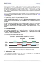
Page 123: ...camera is triggered it begins to integrate and when the integration is over the image data will be read out immediately The MER U3 series camera supports two exposure modes overlapping exposure and n...

Page 124: ...the Nth frame image is reading out the N 1th frame image has been started exposure The formula of overlapping exposure frame period overlapping exposure frame period exposure time readout time Time Ov...

Page 125: ...e is one of the ways to adjust the brightness of the image which is a lot different from a global shutter camera and an electronic rolling shutter camera especially in strobe control All the lines of...

Page 126: ...early the image above will be bright if the strobe is delay to extinguish the image below will brighter The width of the flash signal can be obtained by the following formula Tstrobe Texposure 1 Trow...

Page 127: ...M C L 0 24dB 0dB 0 1dB MER 050 560U3M C L 0 16dB 0dB 0 1dB MER 050 560U3M L NIR 0 16dB 0dB 0 1dB MER 051 120U3M C L 0 16dB 0dB 0 1dB MER 131 210U3M C L 0 16dB 0dB 0 1dB MER 131 210U3M L NIR 0 16dB 0dB...

Page 128: ...onse curve of the camera changes as shown in Figure 8 22 The horizontal axis represents the output signal of the sensor in the camera and the vertical axis represents the gray value of the output imag...

Page 129: ...C L Mono8 Mono10 BayerRG8 BayerRG10 MER 050 560U3M L NIR Mono8 Mono10 MER 051 120U3M C L Mono8 Mono10 BayerRG8 BayerRG10 MER 131 210U3M C L Mono8 Mono10 BayerRG8 BayerRG10 MER 131 210U3M L NIR Mono8 M...

Page 130: ...R 1520 13U3C L BayerGR8 BayerGR12 MER 1810 21U3C L BayerGR8 BayerGR12 MER 2000 19U3M C L Mono8 Mono12 BayerRG8 BayerRG12 Table 8 8 Pixel format that the MER U3 series camera supported The image data s...

Page 131: ...4 of the MSB 16 bits data are set to zero Note that the brightness value of each pixel contains two bytes arranged in little endian mode The format is as follows Y00 Y01 Y02 Y03 Y04 Y10 Y11 Y12 Y13 Y1...

Page 132: ...its of the pixel value and the second byte is the high 8 bits of the pixel value When changing the pixel format the device should stop acquisition 8 3 3 ROI By setting the ROI of the image the camera...

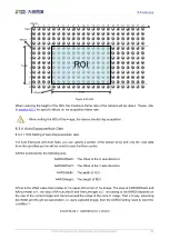
Page 133: ...can specify a portion of the sensor array and only the pixel data from the specified portion will be used for auto function control AAROI is defined by the following way AAROIOffsetX The offset of th...

Page 134: ...ROIOffsetX 100 AAROIOffsetY 50 AAROIWidth 640 AAROIHeight 480 The relative position of the ROI and the image is shown in Figure 8 26 ROI 1024 1000 ROI 640 480 100 50 Figure 8 26 An example for the rel...

Page 135: ...s kept near to the expected gray level The expected gray value is set by the user and it is related to the data bit depth For 8bit pixel data the expected gray value range is 0 255 for 10bit pixel dat...

Page 136: ...height is 1000 and then the white dot area ROI setting is AWBROIOffsetX 100 AWBROIOffsetY 50 AWBROIWidth 640 AWBROIHeight 480 The relative position of the ROI and the image is shown in Figure 8 27 ROI...

Page 137: ...in the frame In the adjacent frame the gray value of the next frame increases by 1 compared to the previous frame until to 255 and then the next frame gray value returns to 0 and so on A printscreen o...

Page 138: ...e of the static diagonal gray gradient test image the gray value in the same position remains unchanged A printscreen of the static diagonal gray gradient test image is shown in Figure 8 30 Figure 8 3...

Page 139: ...ered on again the effective configuration parameters will be lost The vendor default configuration parameters Default Before the camera leaves the factory the camera manufacturer will test the camera...

Page 140: ...nkEnable Load parameters UserSetLoad Load the vendor default configuration parameters or the user configuration parameters into the effective configuration parameters After this operation is performed...

Page 141: ...of the user defined name of each camera otherwise an exception will occur when the camera is opened 8 3 9 Timestamp The timestamp feature counts the number of ticks generated by the camera s internal...

Page 142: ...nning factor are both set to 2 the camera combines the adjacent 4 sub pixels of the same color according to the corresponding positions and outputs the combined pixel values as one sub pixel R G B G R...

Page 143: ...balance ROI will change The changed value is the original value the value before the setting divided by the Binning factor For example assume that you are using a camera with a 1200 x 960 sensor Horiz...

Page 144: ...tion factor of n the camera transmits only every nth pair of rows For example when you specify a vertical Decimation factor of 2 the camera skips rows 1 and 2 transmits rows 3 and 4 skips rows 5 and 6...

Page 145: ...r To configure horizontal Decimation enter a value for the DecimationHorizontal parameter The value of the parameters defines the Decimation factor Depending on your camera model the following values...

Page 146: ...nnot be used When the vertical Decimation value is set to a value other than 1 the vertical Binning feature cannot be used Camera models that support this feature Model MER 031 860U3M C L MER 031 860U...

Page 147: ...nd vertically Figure 8 44 The original image Figure 8 45 Reverse X and Y enabled Using Image ROI with Reverse X or Reverse Y If you have specified an image ROI while using Reverse X or Reverse Y you m...

Page 148: ...igurations etc The user data area is 16K bytes and is divided into 4 data segments each of which is 4K bytes The user can access the user data area through the API interface The data is saved to the c...

Page 149: ...range of TimerDuration is 0 16777215 the unit is s 1 From the start of the timer to the full output of Timer1Active this process will not be interrupted by the ExposureStart signal and Timer1Active m...

Page 150: ...r currently only Counter1 supported 2 Set CounterEventSource the values that can be set are FrameStart FrameTrigger AcquisitionTrigger 3 Set CounterResetSource the values that can be set are Off SoftW...

Page 151: ...Size 106 DeviceLinkThroughputLimit Tacq Texp Among them ImageSize Width Height PixelSize 84 The camera s frame period unit s Width The current image width Height The current image height PixelSize The...

Page 152: ...ent device acquisition bandwidth will be reduced to the limit of the DeviceLinkThroughputLimit the current device acquisition bandwidth can be read from the camera When the camera is working in trigge...

Page 153: ...2 43U3M C L 35000000Bps 8bit 400000000 Bps 1000000Bps 70000000Bps 12bit MER 131 210U3M C L 35000000Bps 8bit 400000000 Bps 1000000Bps 70000000Bps 10bit MER 134 93U3M C L 35000000Bps 8bit 400000000 Bps...

Page 154: ...00Bps 12bit MER 1810 21U3C L 35000000Bps 8bit 400000000 Bps 1000000Bps 70000000Bps 12bit MER 2000 19U3M C L 35000000Bps 8bit 400000000 Bps 1000000Bps 70000000Bps 12bit Table 8 9 MER U3 camera bandwidt...

Page 155: ...ax Width 4 4 84 10 6 The acquisition time unit s Tacq Height Trow 85 5 2 For MER 041 436U3M C L camera Row period unit s Trow 147 37 5 3 92 The acquisition time unit s Tacq Height 32 Trow 3 For MER 05...

Page 156: ...inuous mode the row period unit s Trow 1388 74 25 18 69 In trigger mode the row period unit s Trow 1650 74 25 22 222 The acquisition time unit s Tacq Height 30 Trow 8 For MER 134 93U3M C L camera Row...

Page 157: ...el format is Mono8 or BayerRG8 the row period unit s Trow 180 37 5 4 8 When the pixel format is Mono10 or BayerRG10 the row period unit s Trow 360 37 5 9 6 The acquisition time unit s Tacq Height 38 T...

Page 158: ...C L MER 502 79U3M L POL camera When the pixel format is Mono8 or BayerRG8 the row period unit s Trow 227 37 5 6 053 When the pixel format is Mono10 or BayerRG10 the row period unit s Trow 454 37 5 12...

Page 159: ...the pixel format is BayerRG8 the row period unit s Trow 720 72 10 When the pixel format is BayerRG12 the row period unit s Trow 720 2 72 20 The acquisition time unit s Tacq Height 38 Trow 20 For MER...

Page 160: ...The acquisition time unit s Tacq Height 77 Trow 22 For MER 2000 19U3M C L camera When the pixel format is BayerRG8 the row period unit s Trow 900 72 12 5 When the pixel format is BayerRG12 the row pe...

Page 161: ...al BinningVertical DecimationHorizontal and DecimationVertical please refer to section 8 3 10 and section 8 3 11 These four parameters affect the transmission time of the image data 3 The ExposureTime...

Page 162: ...hout being affected by the AcquisitionFrameRate When using the frame rate calculation tool please fill in the above information of the camera into the corresponding table When the filled value exceeds...

Page 163: ...ned the camera 5 Fail to open device it shows that This device can only be operated on an USB3 0 Port 1 Please check whether the camera is connected to USB2 0 port or USB2 0 HUB Be sure to connect the...

Page 164: ...10 FAQ China Daheng Group Inc Beijing Image Vision Technology Branch 156 9 Camera crashes on Advantech AIIS 1440 IPC 1 Be sure the driver version of AMD USB controller is later than 2 20...

Page 165: ...MER 503 36U3x 2016 11 11 10 V1 0 9 Update section 1 2 and 1 3 2016 12 02 11 V1 0 10 Update MER XXX XXXU3M NIR L to MER XXX XXXU3M L NIR 2016 12 26 12 V1 0 11 Update table 4 2 Update SNR and definition...

Page 166: ...017 11 10 27 V1 0 26 Update gain to MER 051 120U3x 2017 12 22 28 V1 0 27 Add MER 630 60U3x 2017 12 29 29 V1 0 28 Update SNR to MER 051 120U3x Change the company s logo 2018 01 25 30 V1 0 29 Change the...

Page 167: ...0 46 Update SNR and definition for MER 1220 32U3x 2019 01 21 48 V1 0 47 Update definition for MER 133 54U3M Update definition for MER 132 43U3x 2019 02 18 49 V1 0 48 Update definition for these camera...

Page 168: ...ax 010 82563343 Email isales deheng imaging com 2 Shanghai Office Tel 021 35312826 Fax 021 65201839 128 Email shanghai daheng imaging com 3 Shenzhen Office Tel 0755 83479565 Fax 0755 82044020 E mail s...

Page 169: ...Image Vision Technology Branch 161 Email xian daheng imaging com 12 2 Contact Support If you have any questions in using DAHENG IMAGING products please contact the experts on our support team Tel 400...

Reviews: