TBM
PILOT’S OPERATING HANDBOOK
700
SECTION 7
DESCRIPTION
Page 7.3.2
Edition 1 -- November 30, 2010
Rev. 0
An adjustable air outlet is located on both sides of instrument panel lower
part.
Reception--micro jacks are located on the arm--rest on both lateral sides of
the cockpit, on R.H. side of intermediate R.H. passenger’s seat and on the
arm--rest of rear R.H. passenger’s seat (if installed).
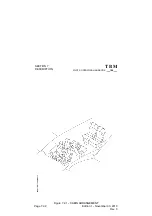
Pedestal console
(Figure 7.3.6)
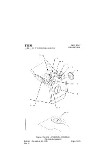
The pedestal console, under the GCU 475 control unit, comprises flaps
controls, pitch trim tab control wheel, aileron trim switch, engine controls and
fuel tank selector.
Circuit breakers panel
(Figures 7.3.7 and 7.8.3)
Circuit breakers for all electrical equipment supplied by bus bars are located
on a separate panel installed on the right side of cockpit.
General alarms warning lights and CAS messages
Warning (red) and Caution (yellow) messages appear on the GDU 1500 MFD
CAS display to alert crew about monitored systems discrepancies. As a
message appears, an aural tone is heard. Refer to the GARMIN G1000
Cockpit Reference Guide to know all possible CAS messages.
A ”MASTER WARNING” red flashing indicator and a ”MASTER CAUTION”
amber indicator located on instrument panel (see Figure 7.3.8) in front of the
pilot, illuminate as soon as one or several messages of same color light on.
To cancel and reset a general alarm, press on the red or amber indicator. A
pressure on the red indicator also stops red message associated aural tones.
Aural warnings
(Figure 7.3.2)
The aural warnings are intended to alert the pilot during some configurations.
The aural signals are heard through the loud--speakers or the buzzer
installed in cockpit overhead panel.
The aural warnings consist of :
-- the aural warning box,
-- the buzzer and loud--speakers.

