TBM
PILOT’S OPERATING HANDBOOK
700
SECTION 7
DESCRIPTION
Page 7.3.8
Edition 1 -- November 30, 2010
Rev. 0
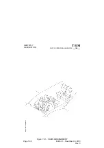
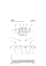
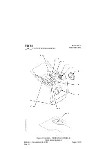
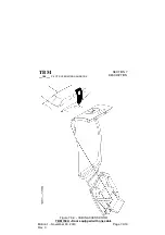
Figure 7.3.3 (1/2) -- LEFT INSTRUMENT PANEL
1) L.H. GMA 1347 audio panel
2) General alarm red and amber
indicators
3) GDU 1040 PFD1
4) Stand--by airspeed indicator
5) Stand--by attitude indicator
6) Landing gear configuration and
control panel (Figure 7.5.1)
7) Parking
brake
control
(Figure 7.5.6)
8) Left station control wheel tube
9) Deicing control and check panel
(Figure 7.13.1)
10) L.H. station rudder pedals
adjusting handle
11) Left station reception--micro
jacks
12) Electric pitch trim control
13) Maps reading tablet
14) Electric rudder trim control
15) ”AP / DISC TRM INT” red
push--button
16) Flight
conditions
and
instruction placard
17) Adjustable air outlet
18) Suction indicator
19) ELT remote control switch
20) Oxygen mask microphone
switch (Figure 7.10.1)


